 Fig 1. Hypar-Tensegrity Dome
Proceedings of the Eighth Conference of Computing in Civil
Engineering and Georgraphic Information Systems Symposium, ASCE,
ed. by Barry J. Goodno and Jeff R. Wright. Dallas, TX, June 7-9 1992.
Abstract
The world's largest cable dome, to be completed for the
1992 football season in Atlanta, will be the centerpiece of the 1996
Olympic Games. Spanning 766 ft x 610 ft (233.5 m x 186 m), it will be
the first Hypar-Tensegrity Dome. This new cable supported teflon-coated
fabric roof is based on the tensegrity principles first enunciated by
Buckminster Fuller and Kenneth Snelson. Because of the large deformation
characteristics of this type of structures, special geometric nonlinear
analysis is required. This paper describes the modelling and the
behavior of the roof for the Georgia Dome under different loadings.
Structural System
The Georgia Dome is the first Hypar-Tensegrity
Dome to be built. In a Hypar-Tensegrity Dome, shown in Fig. 1,
hyperbolic paraboloid fabric panels are attached to a cable net that is
rigidized by the use of tensegrity principles.
Fig 1. Hypar-Tensegrity Dome
The plan configuration of the Georgia Dome is an oval defined by two radii. A ring beam along the outer edge of the roof is supported, on radially sliding bearing pots, by 52 columns projecting up from the seating structure below. Twenty six attachment points spaced about 82 ft (25m) on center around this compression ring serve as the springing points for the cable dome. The top surface of the dome consists of a triangulated network of cables attached together at nodes equally spaced along smaller and smaller meridians located 68, 154 and 250 ft (20, 46 and 75m) from the attachment points on the ring beam. Figure 3 shows that in section the structure appears like a truss in which the bottom chord is discontinuous and is replaced by a series of hoops in plan that link bottom chord nodes.
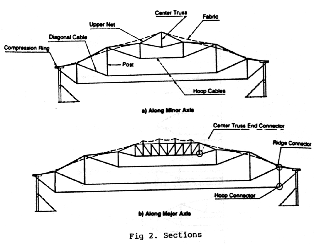 Fig. 2 Sections
These tension hoops are connected to the upper cable net by compression posts and diagonal back-stay cables. A center cable truss ties the two circular ends of the cable net together. The upper cable net is deformed by raising the nodes of alternate meridians to achieve a hyperbolic paraboloid geometry for each of the fabric panels.
Loads
Apart from a low selfweight of about 6 psf (0.3kN/sq.m),
the roof is subject to live load, snow load, wind load, seismic load,
temperature load, and loads imposed on the continuous hoops by catwalks.
In addition, the structure must be analyzed for construction loads
taking into account the erection sequence. Each node is also capable of
supporting a suspended load of 1000 lbs (455kg). The minimum roof live
load is 20 psf (1 kN/sq.m) which can be reduced to 16 psf (0.8 kN/sq.m)
for the design of the fabric and 12 psf (0.6 kN/sq.m) for the design of
the cable net. Wind tunnel tests were conducted by RWDI of Guelph,
Ontario, on a rigid model under conditions simulating the full scale
atmospheric conditions pertinent to the Georgia Dome site. The tests
revealed that no resonance would occur for the range of natural
frequencies of the structure. Fig. 3 shows the first four vibration
modes, which correspond to frequencies of 0.441, 0.682, 0.716, and 0.725
Hz for the prestress and dead load condition. The mean wind loads for a
50-year wind speed, shown in Fig. 4, indicate suction over the entire
surface of the roof because of its flat profile.
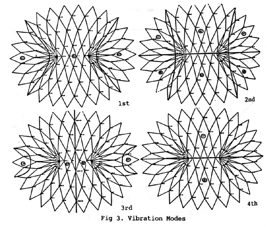 Fig 3. Vibration modes.
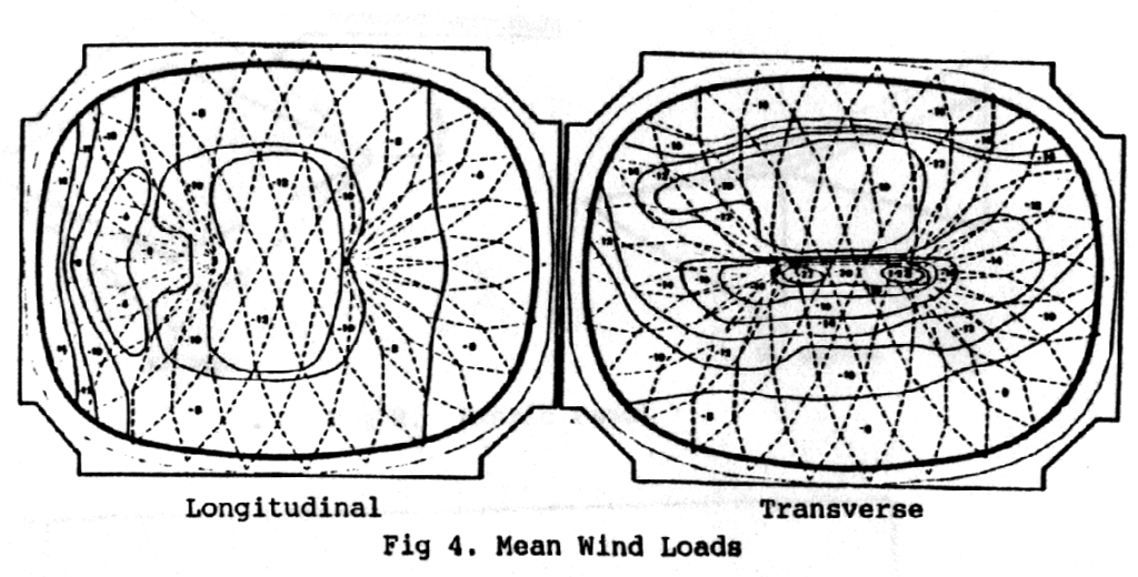 Fig 4. Mean wind loads.
Prestress
If built based on the initially defined geometry, the
cable dome would seem like a limp noodle even under its own weight.
Therefore, a cable dome needs to be prestressed to compensate for the
tendency of some cables to go slack. In order to simulate the prestress
condition computationally, the simple device of introducing a
temperature change in members was employed. A nonlinear analysis using
LARSA was performed on the complete cable dome. If the results indicated
that some cables were in compression, a local temperature change was
applied to those members and the problem was rerun. The runs were
repeated to iterate to a condition where no compression cables existed.
It was determined that an initial prestress averaging 30% of cable
capacity was needed to rigidize the structure. Since the deformation of
the structure was well within normally accepted criteria, it was not
necessary to use additional prestress.
Behavior
The results of the analysis for the first loading
condition, prestress plus dead load, are shown on Fig. 5. From these
results, it is apparent that much of the load on the roof gravitates
toward the four corners as can be seen by the ridge and diagonal cable
forces. Forces in the hoop cables remain relatively constant which
allows the clamping detail to be relatively small. On the other hand,
forces in the ridge cables decrease markedly toward the center. This
implies large changes in the force at a top node and therefore the need
for large clamping forces to absorb the change in tension in the
continuous cables. The shape of the moment diagram for the compression
ring confirms the fact that the four corners of the roof structure
attract much of the roof load. Obviously, in alternate configurations,
as the oval shape tends toward a circle, moments would disappear as the
circle becomes the funicular for the loads.
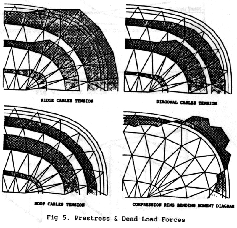 Fig. 5 Prestress & dead load forces.
The design of the top cable net, ridge cables, was controlled by the wind load, while the design of the diagonal and hoop cables was controlled by the live load. Since the dead load of the roof is very low, seismic loads do not affect the cable design and must be considered only for the supporting column design. The bearing posts that support the compression ring allow for free radial displacements so that the effect of the temperature variations is minimized. Maximum displacements in the cable net were found to be 2.5 ft (0.75 m) down and 2.4 ft. (0.72 m) u pfor live load and wind load, respectively.
Construction Sequence
The design of the cables and the
connections must consider the construction sequence, that in the case of
the Hypar-Tensegrity Dome results in large changes in forces and in
geometry requiring a complex 3-D nonlinear analysis. The first step is
to hang the ridge net from the compression ring and then install a
diagonal cable at a time with its corresponding post and hoop cable.
Results from a simplified 2-D model using LARSA are shown in Figs 6 and
7 for the variation in roof geometry and in tension force in the
diagonal cables. These results assume that the first diagonal to be
installed is the outermost, D4, and the last one is the innermost, D1.
The sequence can be altered in order to minimize the maximum required
jacking force.
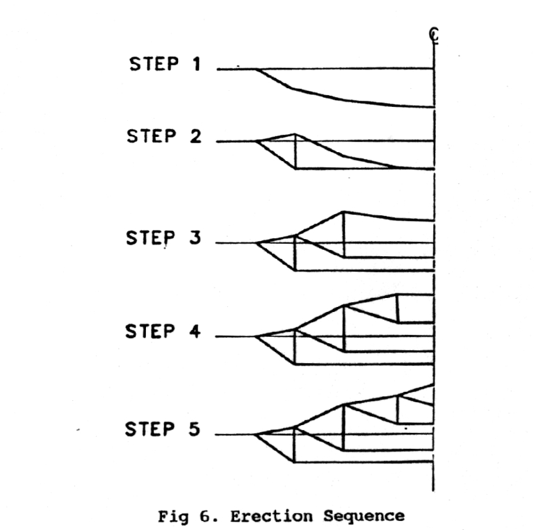 Fig. 6. Erection sequence.
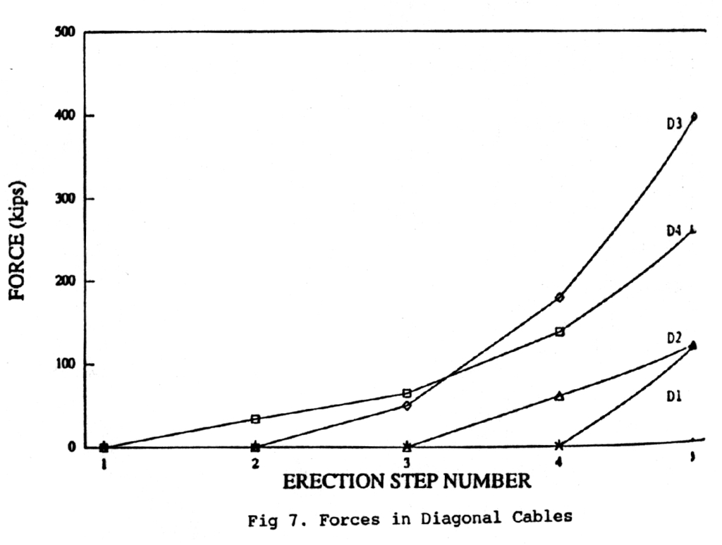 Fig. 7. forces in diagonal cables.
Optimization
In order to verify the choices made in the initial
stages of the project, when time constraints did not allow for geometry
optimization, and to provide guidelines for future development of the
Hypar-Tensegrity Dome concept, an optimization study was prepared with
the objective of defining the most economical geometric configuration.
Three factors were considered: sector width, the post height, and the
number of rings. These are obviously interdependent as exemplified by
considering increasing sector width, which requires the membrane
curvature to be increased, as shown in Fig. 8, to remain within
permissible stresses. An optimal configuration was sought using cost as
the ultimate criterion. A parametric nonlinear analysis using LARSA was
performed using varying post heights and ring spacing. The results shown
in Figs. 9 and 10 suggest that an increase in post height over that used
for the Georgia Dome may result in a lower cost configuration. It is
also apparent that a two ring solution may be more economical than the
three ring configuration used.
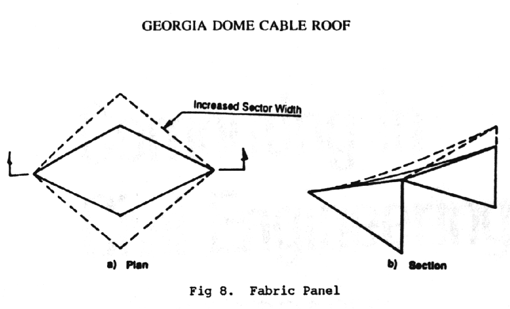 Fig. 8. Fabric panel.
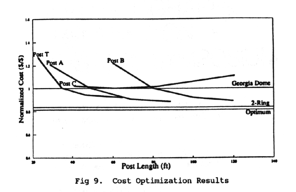 Fig. 9. Cost optimization results.
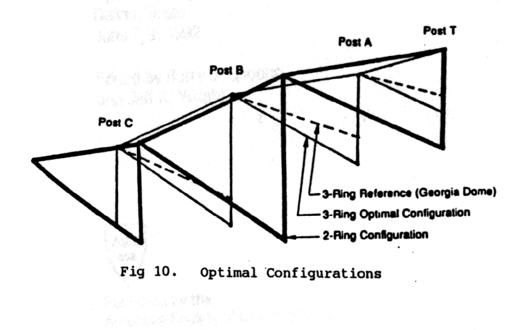 Fig. 10. Optimal configurations.
Conclusions
Structures such as the Hypar-Tensegrity Dome require
special analysis and could not have been realized without the
availability of computers and nonlinear programs. Without computers,
only rough approximations of the forces in such a highly indeterminate
structure could be obtained and furthermore only solutions for
symmetrical or other simple loading conditions could be studied. A
software package like LARSA provides not only the answer to the every
day analysis and design problem but also the nonlinear solutions that
large deformation structures require. This leads to the ability to
economically construct complex structures which would not otherwise be
feasible, opening the door to an exciting range of possibilities limited
only by the creativity of the engineer.