 Figure I. (a) to (d) Variations in
lamella frames.
Figure I. (a) to (d) Variations in
lamella frames.a- top left
b- top right
c- bottom left
d- bottom right
Figures 2,3 and 4 depict timber Lamella domes which are combinations of the Type I shown in figures 1a and 1b...
excerpt from Space Structures, Davies, R.M., ed. New York: John Wiley & Sons, 1967.
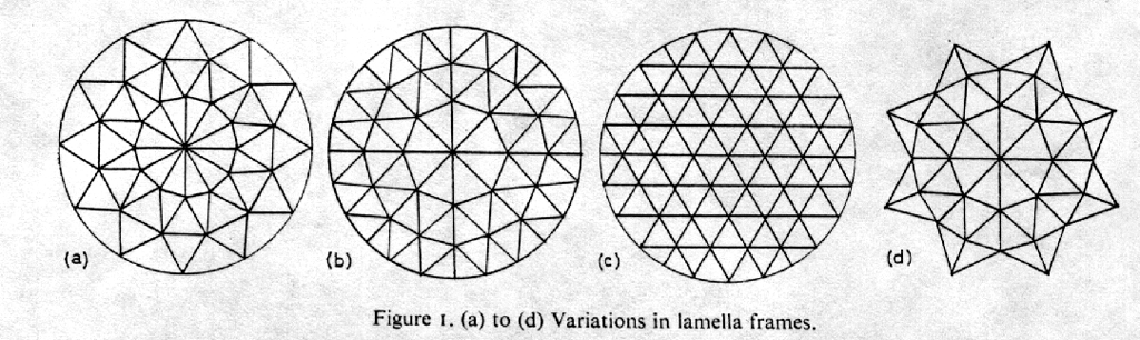
Some variations in pin jointed dome patterns are shown in figures 1a to 1d. The frames shown in 1a and 1b are of Type I in its most commonly built form. The largest Type I dome to date is approximately 240 ft. in diameter.
Figure I. (a) to (d) Variations in
lamella frames.
a- top left
b- top right
c- bottom left
d- bottom right
Figures 2,3 and 4 depict timber Lamella domes which are combinations of
the Type I shown in figures 1a and 1b...
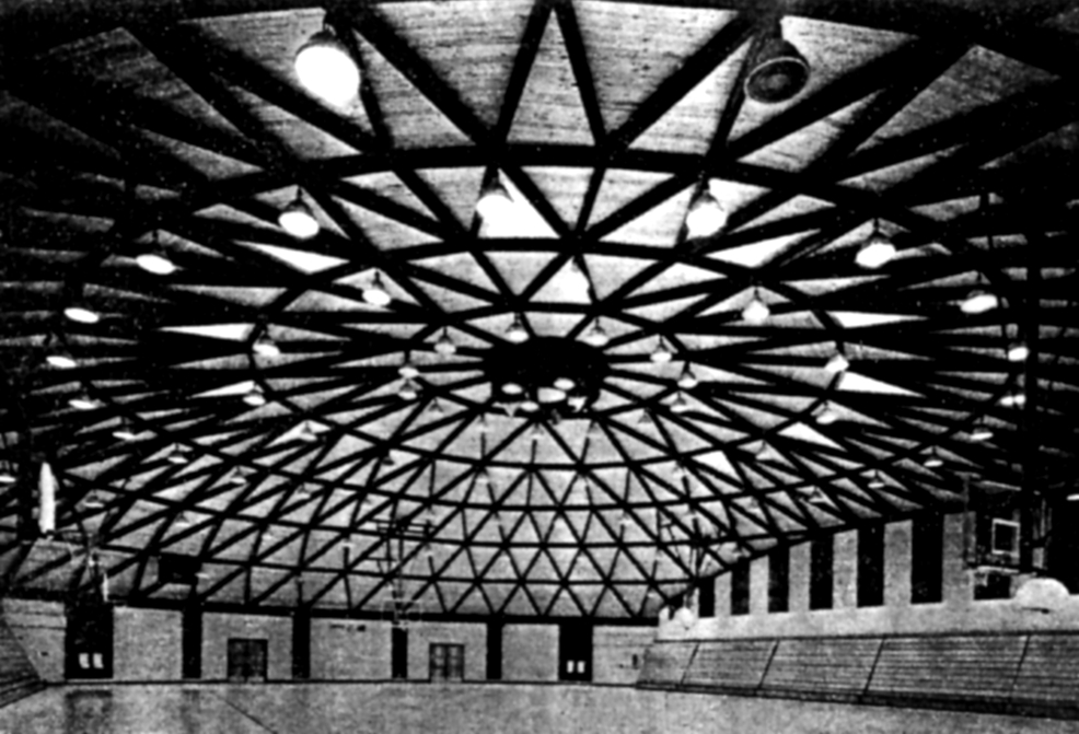 Figure 2. Gymnasium, St. Joseph,
Missouri.
Figure 2. Gymnasium, St. Joseph,
Missouri.
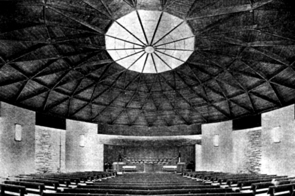 Figure 3. Church, Ft. Lauderdale,
Florida.
Figure 3. Church, Ft. Lauderdale,
Florida.
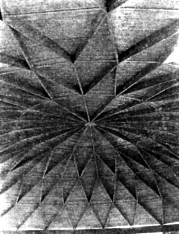 Figure 4. Auditorium, Frederick,
Oklahoma.
Figure 4. Auditorium, Frederick,
Oklahoma.
Figures 5 to 8 depict two steel domes similar to the type shown in figure 1b. Figures 5 to 7 are illustrations of the Harris County Sports Stadium located in Houston, Texas. The architects for this structure were Lloyd & Morgan - Wilson, Morris, Crane & Anderson, and the consulting engineers for the dome structure were Roof Structures Inc., St. Louis, Missouri, with whom the author is associated.
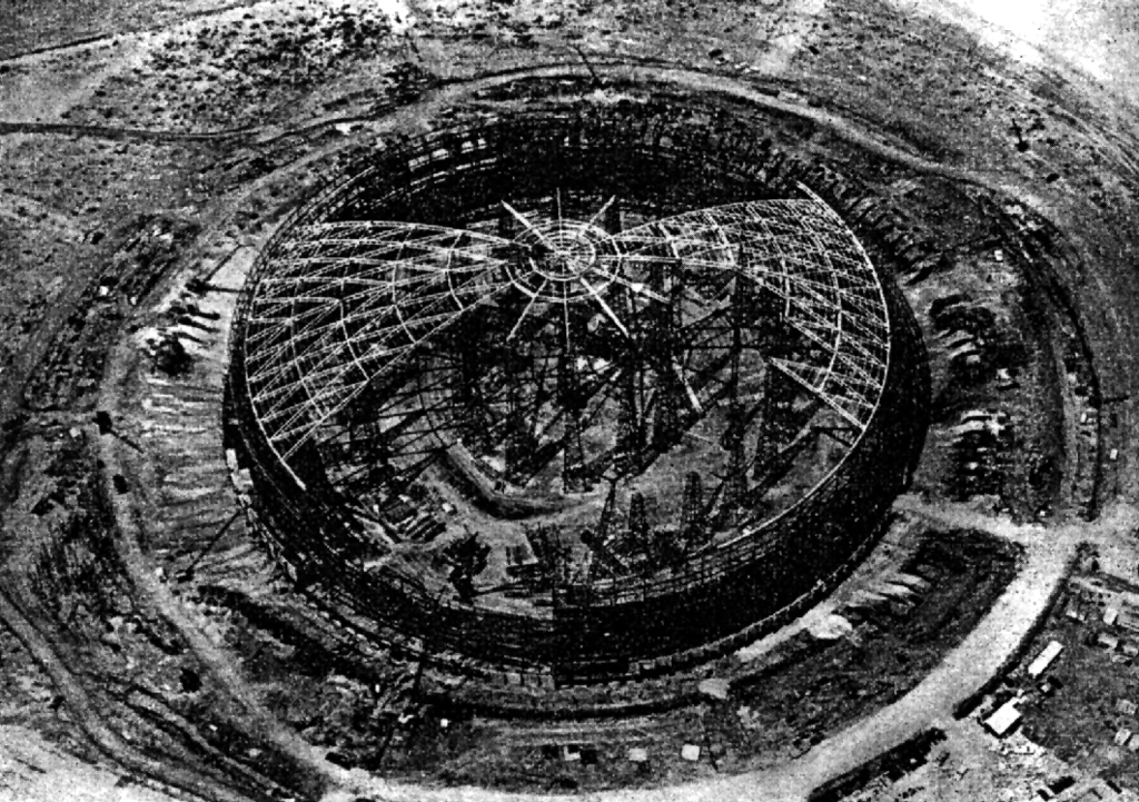 Figure 5. Sports stadium, Houston,
Texas.
Figure 5. Sports stadium, Houston,
Texas.
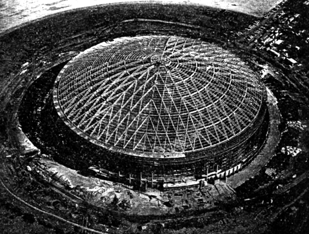 Figure 6. Sports stadium, Houston,
Texas.
Figure 6. Sports stadium, Houston,
Texas.
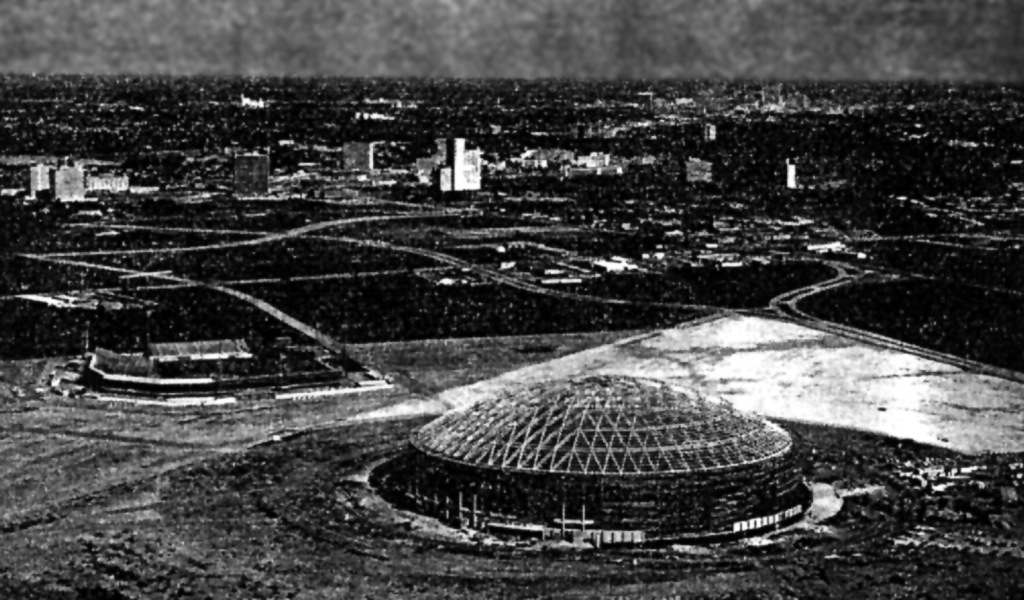 Figure 7. Sports stadium, Houston,
Texas.
Figure 7. Sports stadium, Houston,
Texas.
Figure 8 is a 270 ft. diameter steel Lamella, Type II frame, located in Green Bay, Wisconsin.
 Figure 8. Auditorium, Green Bay,
Wisconsin.
Figure 8. Auditorium, Green Bay,
Wisconsin.
The roof deck for these domes is non-structural, but the sub purlin arrangement furnishes secondary bracing for the dome framing. Both installations are supported on columns pinned radially and fixed tangentially at the outer ring. In the Houston dome, temperature variations displaced the sunward columns by as much as 2 inches radially at their tops in an effective length of 6 ft. 0 in. This action presented some problems in the plumbing of the columns during erection. Thiry-seven temporary erection towers were used for scaffolding, and the longer Lamella units were required to be in excess of 120 ft in length in order to span between scaffold towers. Special cranes with boom length up to 275 ft. were used to lift units up to the 210 ft clear center height. The weight of the roof structure including the outer (tension) ring was slightly less than 16 lbs/sq.ft.
The preparation of the Houston dome analysis was an interesting experience in engineering consultation. The author headed the research team at Roof Structures Inc. and prepared three test models. Two of the models were instrumented with electric strain gauges and loaded to determine the validity of the method of analysis. One of the structural models is shown in figure 9. Test data indicated that the analysis for the model had an error of less than 20 per cent. This error was partially due to model fabrication inaccuracies and instrumentation of the model.
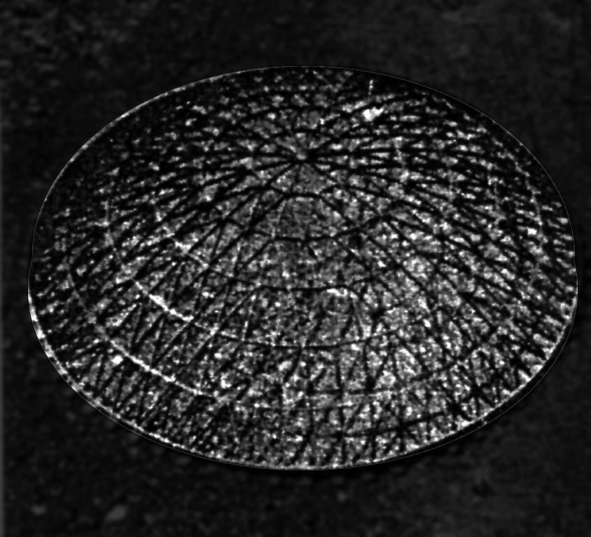 Figure 9. Test model for Houston, Texas.
The third model was fabricated to scale and represented the surface of the stadium for wind tunnel tests. 48 runs of different variety were made and the wind forces idealised for design application to the real structure. Results generally agreed with data in the ASCE publication Wind Bracing in Steel Buildings, Final Report of Sub-Committee No. 31 (Trans. Am. Soc. civ. Engrs, 105, 1713-1739, 1940.). The consulting firm of Walter Moore, Houston, Texas, selected the live load conditions which were 15 lbs/sq.ft snow load and 130 mph wind velocity.
Roof Structures engaged Z.S. Makowski, Dean, Faculty of Engineering,
University of Surrey as consultant to check the analysis. Praeger,
Kavanaugh & Waterbury, Consulting Engineers, New York were engaged by
the architects for a second check of the analysis.
Back to Astrodome: Published Commentary