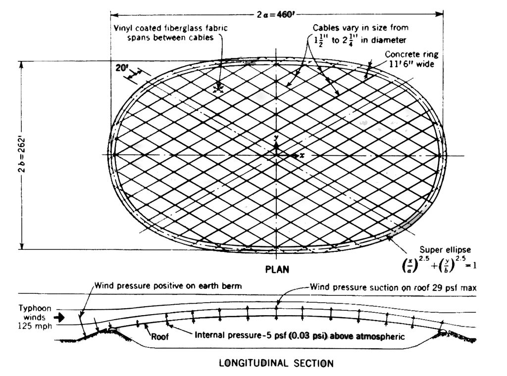
 Figure 1
The roof in plan and section.
The U. S. Pavilion for EXPO 70 in Osaka, Japan features a roof covering 100,000 sq ft with a clear span of 262 by 460 ft. The total weight of the air-supported portion is about one pound per square foot. The high-strength steel cables, varying in diameter from 1 1/2" to 2 1/4", are 20 ft on center, up to 450 ft long, and are arrayed in a diamond grid. There is no tension ring. The cables are anchored to a funicular (no bending moments under normal loading) concrete compression ring resting on, but not anchored to an earth berm. In plan the roof's shape follows the equation of a super-ellipse (an ellipse with square corners) of exponent 2.5. This shape was selected for esthetic reasons.
Evolution of the design
The design evolved from a tight structural budget of $2.6 million for the
U.S. Pavilion. It was suggested that one way to reduce costs would be to work
around certain problems at the site - including the necessity of designing for 150
mph typhoon winds.
An air-supported structure had been the plan of the design team from the beginning, partly because in the original scheme it was intended to project giant-screen films on the inner surface of the resulting dome.
It is difficult to design a large clear-span roof structure at low cost to resist 150 mph winds. The best solution is to take the structure away from exposure to the wind. A cable roof is one possibility. Even better is an air supported cable roof since it has a more aerodynamic cross-section and the cables are better oriented to resist wind forces (see Fig. I ). The cables make possible a very shallow dome (only 23 ft rise over a 262 ft span). Because the structure is low, Japanese codes permit a reduced typhoon wind design speed of 125 mph.
Figure 1
The roof in plan and section.
In order to study the aerodynamic properties of the roof a l/lOOth dynamic model was constructed and tested in a wind tunnel. Under laminar flow no flutter existed with winds up to 200 mph. Under conditions of extreme turbulence slight flutter existed at winds of 131 mph. By increasing the air pressure within the structure, the frequency of these roof vibrations is increased and their amplitude is decreased.
To make the structure still more aerodynamic, an earth berm 20 ft wide and of shallow slope was selected. The outside face is covered with brown asphalt pavers set in lean concrete, and the interior face with Mylar plastic sheeting. The latter provides a rippling mirror effect and reflects daylight onto the roof.
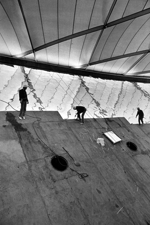 Installation of Mylar plastic sheeting
Image courtesy Davis-Brody
This cross-section of berm and roof led to a wind-pressure distribution that is positive (downward) on the berm and negative (upward) over the cable roof surface(Fig. 1).
It was decided not to deploy the cables in the usual radial fashion with a central tension ring. The weight of the ring might have caused a "dimple" in the center of the air-supported roof. Had rain gathered there, it might have led to collapse. Also, with radial cables, there are twice as many end fittings, plus the cost and weight of a tension ring, plus the necessity of obtaining roof fabric to span wide distances at the roof's circumference and narrow widths at the center.
Originally it was planned to array the cables on a rectilinear grid, that is parallel to the major and minor axes of the super-ellipse, as with a tennis racquet. However, it was found that the diamond grid selected led to the savings of 33 percent in cable tonnage.
Three different diameters of wire cables of ASTM standard, 1 1/2", 1 1/8", and 2 1/4", are employed. There are 32 cables, each containing 92 strands. The intersection points of cables were precisely determined by computer, and marked on each cable at the fabrication plant.
Cable ends are fixed into sockets with zinc alloy filler, and anchored into the concrete compression ring. Design safety factor of the anchorage against proved breaking load of cable under short-period loading is 2.6.
The compression ring (Fig 2) is not tied to the concrete base beneath it. It was designed to have sufficient mass to prevent uplift with a factor of safety of 1.6 Between the base and the compression ring is a galvanized steel sheet, used to obtain a coefficient of friction of 0.4. This coefficient was chosen so as to prevent the ring from sliding off the base under a seismic load or typhoon wind load, yet to permit sliding due to instabilities induced by oscillations in the roof structure caused by high, gusty winds. Sliding of the rind under dynamic loading will serve to dampen cable and roof motion. Maximum suction under typhoon wind loading (125 mph) is 24.8 psf.
 Figure 2
Cross-section of compression ring. Ring rests on a concrete base but is
not anchored to it; a galvanized steel sheet between ring and base
provides a friction coefficient of about 0.40. The fabric anchor is
designed to eliminate point loads on the membrane, which could cause
ripping; this is also the function of the fabric skirt between membrane
and cables.
Roof covering
The roof covering consists of a fine-threaded fabric of close-woven glass
fibers, coated on both sides with vinyl to provide air and water tightness.
The glass fabric was developed for use in astronaut space suits, after three U.S. astronauts were killed by a fire while locked in their capsule on a launch pad at Cape Kennedy. The fabric has a 1,000 deg. F melting point. The vinyl coating does melt at a lower temperature. A fire test of the fabric was conducted. A gasoline fire atop the roof was put out by the air rushing out through the now-porous glass fabric (after the vinyl had melted). The fire in no way damaged the glass fabric, and it was ready for recoating with vinyl and for reuse.
The fabric, about 3/32" thick, has a strength of 800 pounds per inch. Like any fabric, it must be employed in a structure with the knowledge that point loads, i.e. stress concentrations, can cause ripping. For this reason, fabric details were developed at the ring and between the membrane and cables so as to distribute the load uniformly to the fabric structure.
Roof erection
Erection of this 100,000 sq ft roof was straightforward. Falsework
was erected to a level a few feet beneath the cable-anchor level, and
wood planks were laid atop the falsework. This provided a working
platform for roof assembly, but more important from the standpoint of
scheduling it made possible simultaneous work on the exhibit structures
beneath.
First the cables were placed, and clamped at the precise location of their intersections, as premarked on the cables. Then the fabric, pre-assembled with skirts in place, was placed over the cables. Workers laced the fabric skirts to the cables. Then the roof was inflated. No adjustments to cables were required at either the cable crossing points or at the end anchorages.
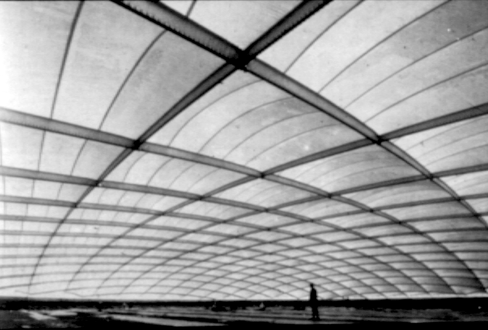
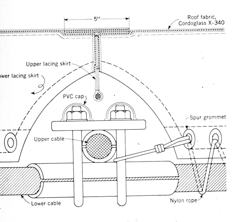 Figure 3
Cable crossing and lacing-skirt detail. Most joining of fabric to
fabric is by heat sealing with the same vinyl which covers the glass
cloth membrane. On cable-clamp nuts are PVC (polyvinyl chloride) caps
to eliminate possibility of tears.
Air pressure
The roof is tensioned by an internal pressure of about 0.03 psi.
This results in an overall rise of about 23 ft. Pressure is normally
maintained by four blowers, each with 8,000 cfm capacity. Two additional
blowers of the same capacity are held in reserve. In case of a power
failure, there exists an emergency generator for the pressurization
system. Also, should the roof collapse the steel framework of
the exhibit structure below would hold the roof above visitors' heads.
Lighting
The white, translucent roof material means that, during the day,
sky light will softly illuminate the pavilion. At night, interior
lighting will provide an interesting view of the roof for people
outside. Fluorescent lights placed just inside the edge of the roof
provide perimeter lighting at night.
Costs
The structure cost $2.6 million, including an 18,000 basement office area
of conventional concrete construction under the Pavilion floor. This
contrasts with the $5 million structure budget for the U.S. Pavilion at
Montreal's EXPO 67, which featured a geodesic dome (Civil Engineering,
March 1967, cover and pp. 40-51).
The roof of the U.S. Pavilion in Osaka cost $3 per sq ft for the fabric, $1 per sq ft for the cable, and $0.50 per sq ft for the ring, for a total of $4.50. This does not include the earth berm. The structure's low cost results in part from the absence of a foundation and structure of the conventional sort.
The cost of air pressure to keep the roof inflated is not great. The amount of blower capacity required is independent of volume, and depends only on the amount of leakage. The pavilion has revolving doors. The cost of air pressure is little more than the air conditioning cost, when that is required.
However, the vinyl used in coating the fabric, and as adhesive in bonding fabric and skirt together, undergoes ultraviolet deterioration and has a life of 7 to 10 years. The cost of replacing the fabric, perhaps $300,000 is an important consideration.
It is believed that the state of the art in plastics is advancing at such a rate that in 10 years the replacement fabric will be improved so much as to be essentially permanent.
 Interior view of U.S. Pavilion.
Lines of dripping water on berm and floor are caused by dripping from
cables, where water condensed on a cold day; this ceased when air
conditioning was turned on.
Interior view of U.S. Pavilion.
Lines of dripping water on berm and floor are caused by dripping from
cables, where water condensed on a cold day; this ceased when air
conditioning was turned on.
Assessment
The U.S. Pavilion at Osaka is the largest clear span, air supported roof
ever built. It is one of the first clear span, air supported roofs ever
built, and the first without a compression tension ring, the first roof
of any material having a super-elliptical ring, and the lightest roof of
the span ever built.
It is believed that air-supported cable roofs can be successfully used wherever a controlled environment is wanted. One good possibility is stadiums built without a roof, but whose owners would now like to add a roof in order to increase the number of days (and uses) of their property, and to provide greater spectator comfort. There appears to be no maximum span for application of this type of roof: studies do indicate that it is not economically advantageous much below 150 ft span.
Credits
The U.S. Pavilion was designed for the U.S. Information Agency by
the design team of Davis, Brody, Chermayeff, Geismar, deHarak
Associates, New York City. Structural engineers are David Geiger-Horst
Berger. General contractor is Ohbayashi-Gumi Lid., Osaka. Supplier of
the roof fabric is Composite Division, Ferro Corp., Norwalk, Conn. Roof
fabricator is Taiyo Kogyo Corp., Japan. Cable supplier is Shinko Wire
Co., Ltd., Japan.
Dr. Geiger is assistant professor of Columbia University School of Architecture. He directed a research program at the American Iron and Steel Institute on the economics of cable roofs, domes and space stresses, spanning from 100 to 1,000 ft. He began a private practice in 1964 and formed a partnership with Horst Berger in 1968.
Back to Osaka: Published Commentary