Construction Documents
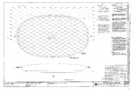
Roof Details, Drawing PS-2
-
-
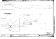
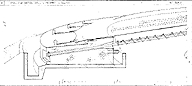
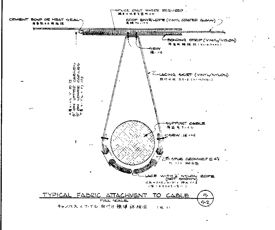
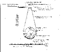 Typical Fabric Attachment to Support Cable
Detail 5
-
-
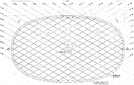
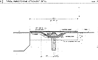
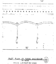 Partial Plan of Fabric Anchorage
Detail 6
-
-
 Nylon Rope Bolted Through Fabric
Detail D
-
-
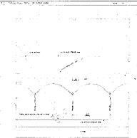
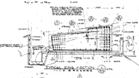 Typical Ring Section
Detail 1
-
-
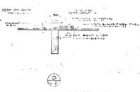
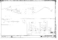
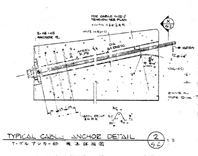 Typcial Cable Anchor Detail
Detail 2
-
-
 Typical Detail at Cable Crossing
Detail 3
-
-
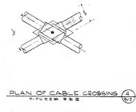 Plan of Cable Crossing
Detail 4
-
-
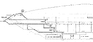
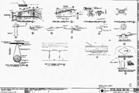 Roof Details
Full Document: PS-2
1.5M JPEG
-
-
Roof Details
Full Document: PS-2
17M TIF
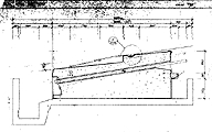
HVAC: AC-007
-
-
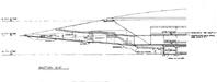
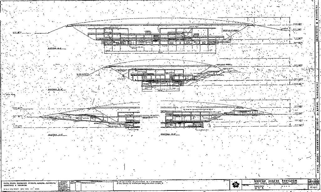
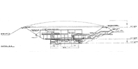 Section B-B
Egress, Exhibit Structure,
Supply Duct Sections
-
-
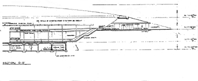
 Section C-C
Egress, Fresh Air Chamber
Sections
-
-
 Section D-D
Entrance, Interior Stair
Air Conditioning Unit
Sections
-
-
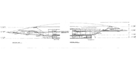 Sections C-C and D-D
-
-
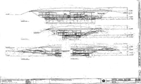 HVAC AC-007
Full Document: 2.5M JPEG
-
-
HVACAC-007
Full Document: 18M TIF
Plan and Elevation, Drawing M-1
-
-
 Plan and Elevation
Full Document: MB JPEG
-
-
Plan and Elevation
Full Document: MB TIFF
-
-
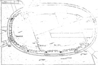 Detail of Plan at 184'
Detail from sheet M-1
-
-
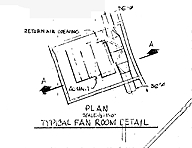 Typical Fan Room Detail
Detail from sheet M-1
-
-
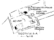 Section AA: Typical Fan Room
Detail from sheet M-1
Mechanical Systems Diagram, Drawing AC006
-
-
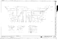 Mechanical Systems Diagram
Full Document: MB JPEG
-
-
Mechanical Systems Diagram
Full Document: MB TIFF
-
-
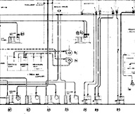 Mechanical Systems Diagram
Detail of Document AC006
-
-
 Exhibition, Offices Control System
Detail of Document AC006
-
-
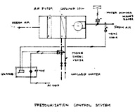 Pressurization Control System
Detail of Document AC006
Upper Exhibition Levels, Drawing AC004
-
-
 Upper Exhibition Levels
Full Document: MB JPEG
-
-
Upper Exhibition Levels
Full Document: MB TIFF
-
-
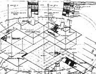 Exhibition Level Plan Detail
Detail of Document AC004
Roof Strucure, Drawing PS-1
-
-
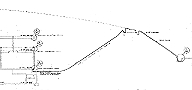
 Roof Structure
Full Document: MB JPEG
-
-
Roof Structure
Full Document: MB TIFF
-
-
 Reflected Ceiling Plan: Detail
Detail from sheet P-S1
Roof Details, North and West Elevations, Drawing PA-9
-
-
 Roof Details, North and West Elevations
Full Document: MB JPEG
-
-
Roof Details, North and West Elevations
Full Document: MB TIFF
-
-
 Typical Ring Sction
Detail of Document P-A9
-
-
 Typical Fabric-To-Ring Attachment Detail
Detail of Document P-A9
-
-
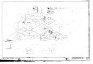
 Typical Ring Section Detail in Perspective Sketch
Detail of Document P-A9
-
-
 Typcial Plan Detail of Roof Edge
Detail of Document P-A9
Section AA and Details, Drawing PA-6
-
-
 Section AA and Details
Full Document: MB JPEG
-
-
Section AA and Details
Full Document: MB TIFF
-
-
 Section AA (left side of section)
Detail of Document P-A6
-
-
 Formwork for Vertical Board Finish Core
Detail of Document P-A6
-
-
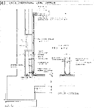 U.S.I.A./ Mechanical Level Details
Detail of Document P-A6
-
-
 Section AA (right side of section)
Detail of Document P-A6
Site Plan, Drawing PA-1
-
-
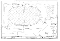 Site Plan
Full Document: MB JPEG
-
-
Site Plan
Full Document: MB TIFF
-
-
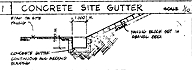 Concrete Site Gutter
Detail of Document P-A-1
-
-
 Back to How It Works Menu
 Typical Fabric Attachment to Support Cable
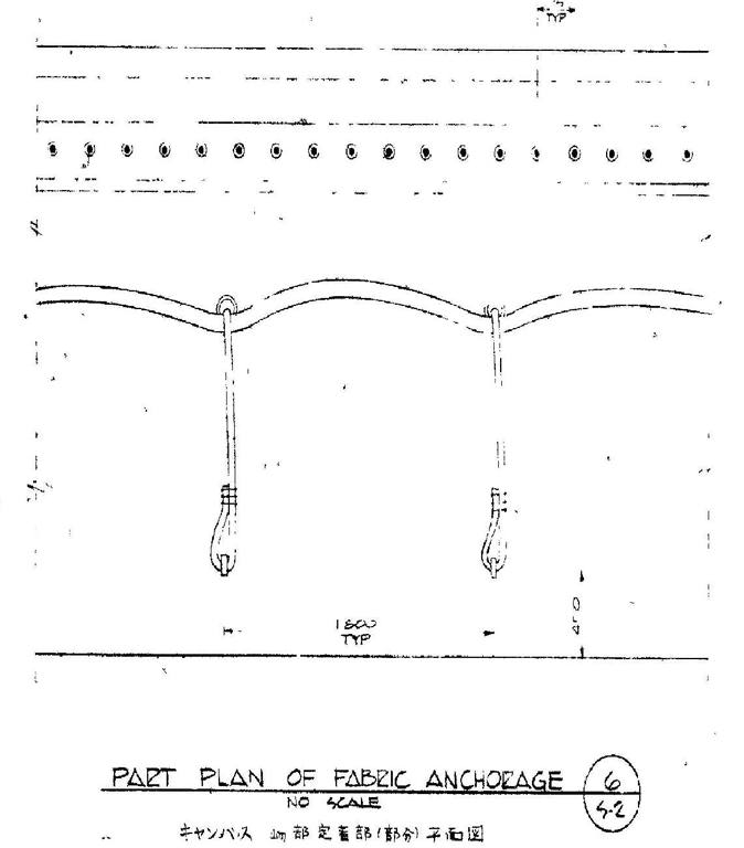 Partial Plan of Fabric Anchorage
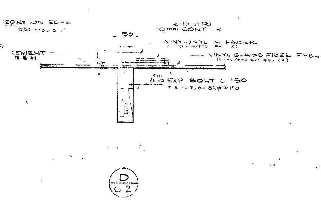 Nylon Rope Bolted Through Fabric
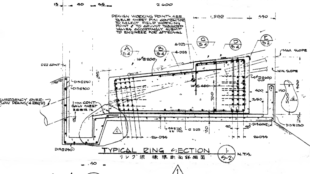 Typical Ring Section
 Typcial Cable Anchor Detail
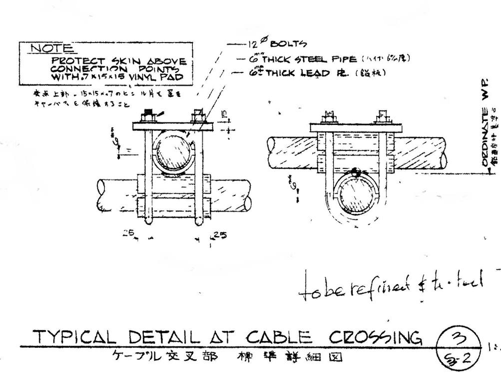 Typical Detail at Cable Crossing
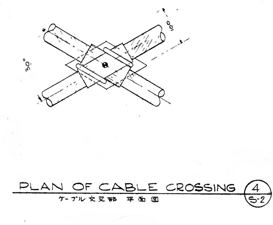 Plan of Cable Crossing
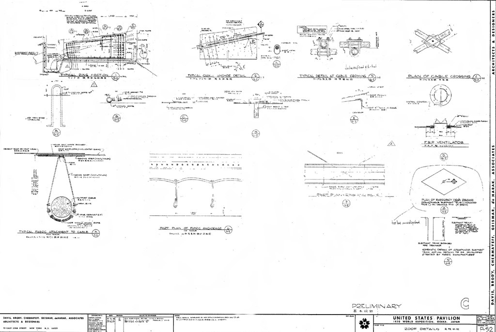 Roof Details
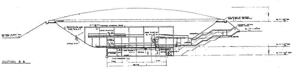 Section B-B
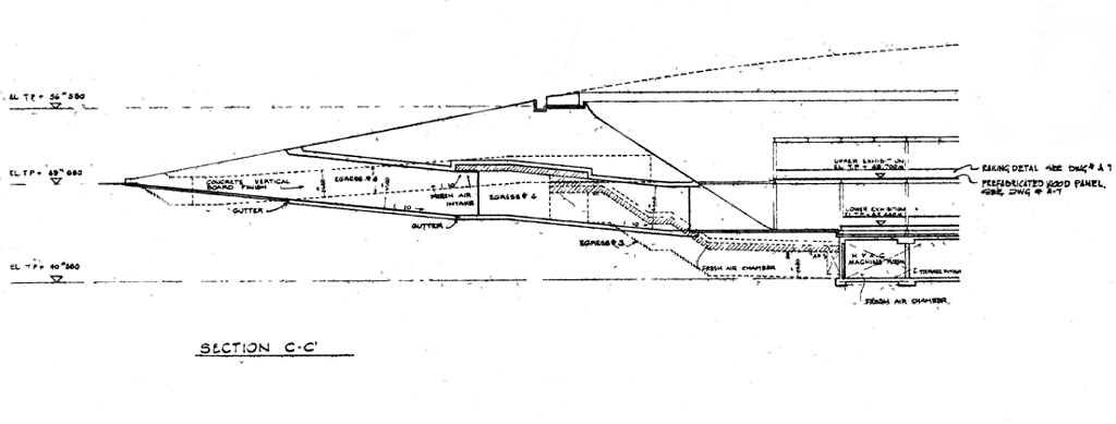 Section C-C
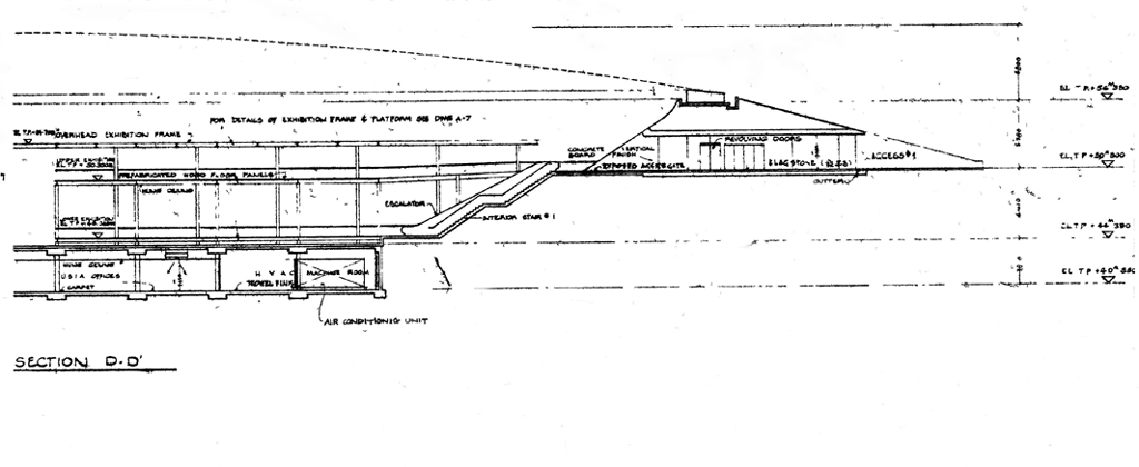 Section D-D
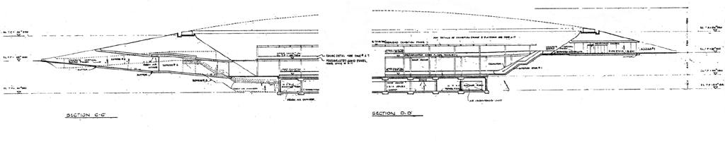 Sections C-C and D-D
 HVAC AC-007
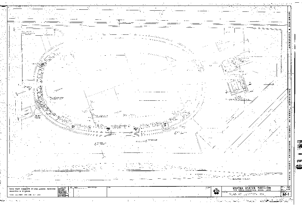 Plan and Elevation
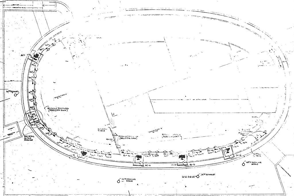 Detail of Plan at 184'
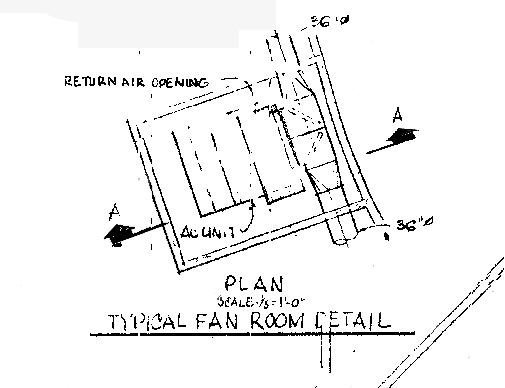 Typical Fan Room Detail
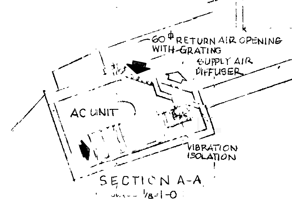 Section AA: Typical Fan Room
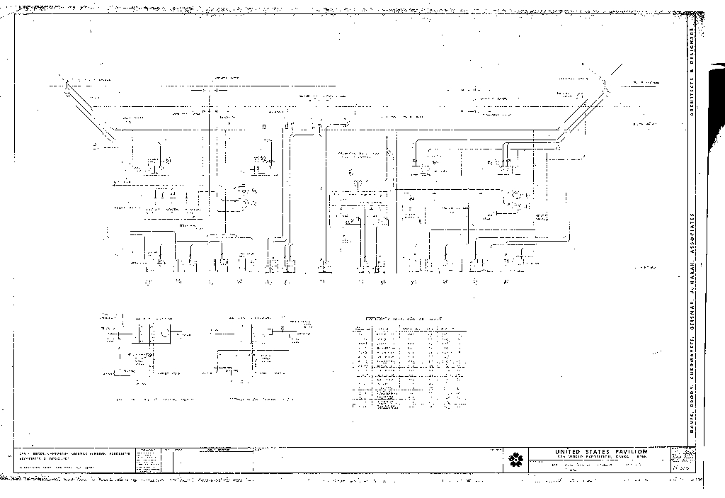 Mechanical Systems Diagram
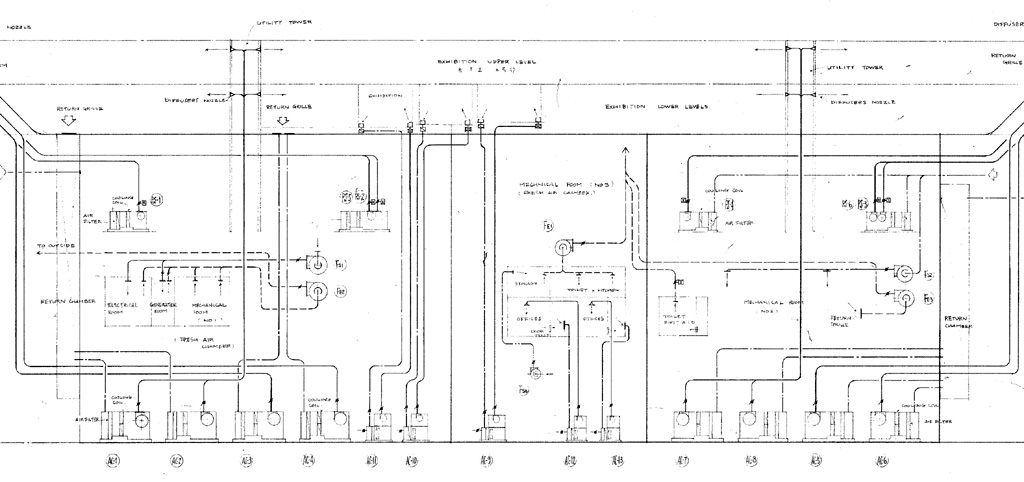 Mechanical Systems Diagram
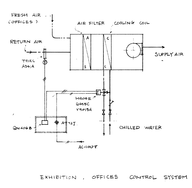 Exhibition, Offices Control System
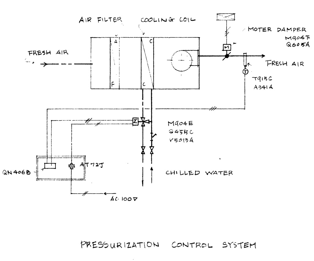 Pressurization Control System
 Upper Exhibition Levels
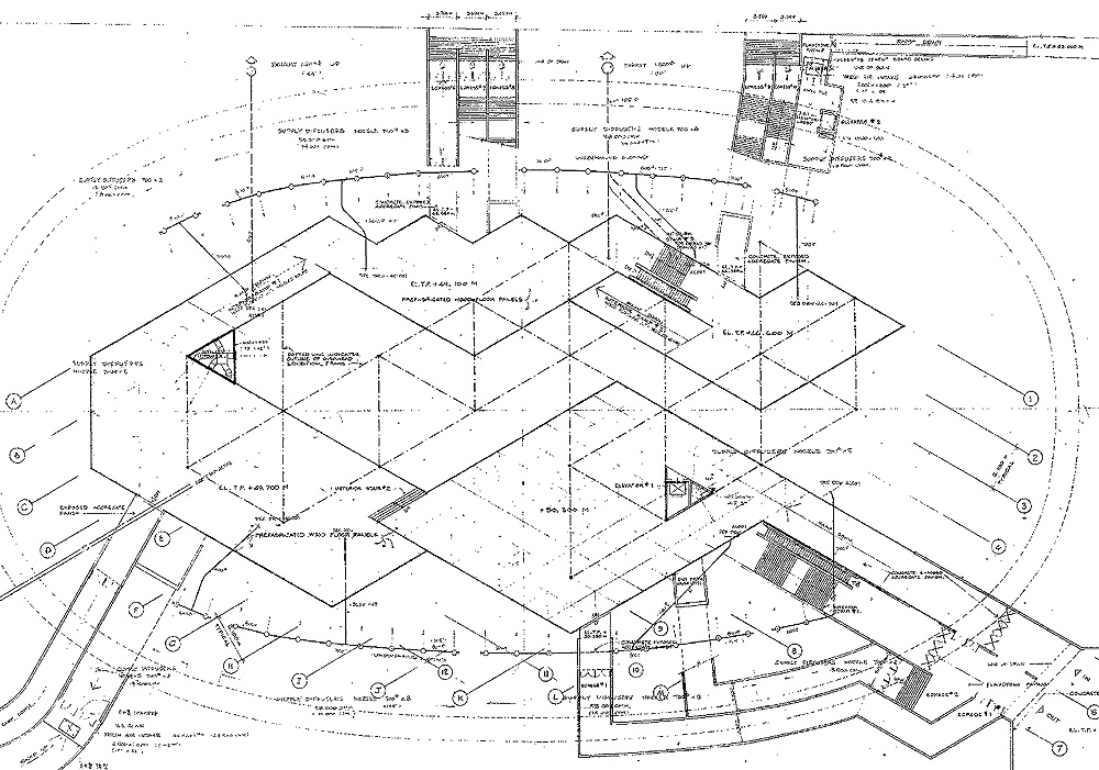 Exhibition Level Plan Detail
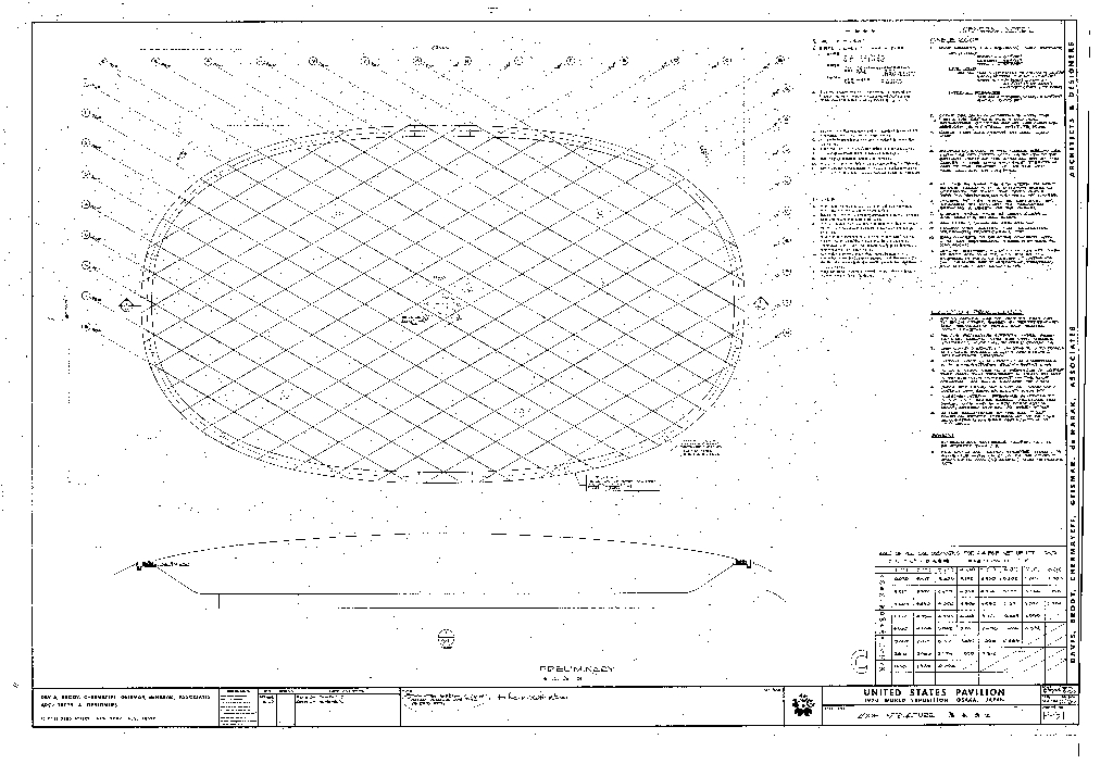 Roof Structure
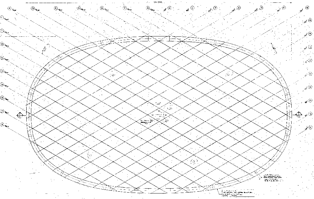 Reflected Ceiling Plan: Detail
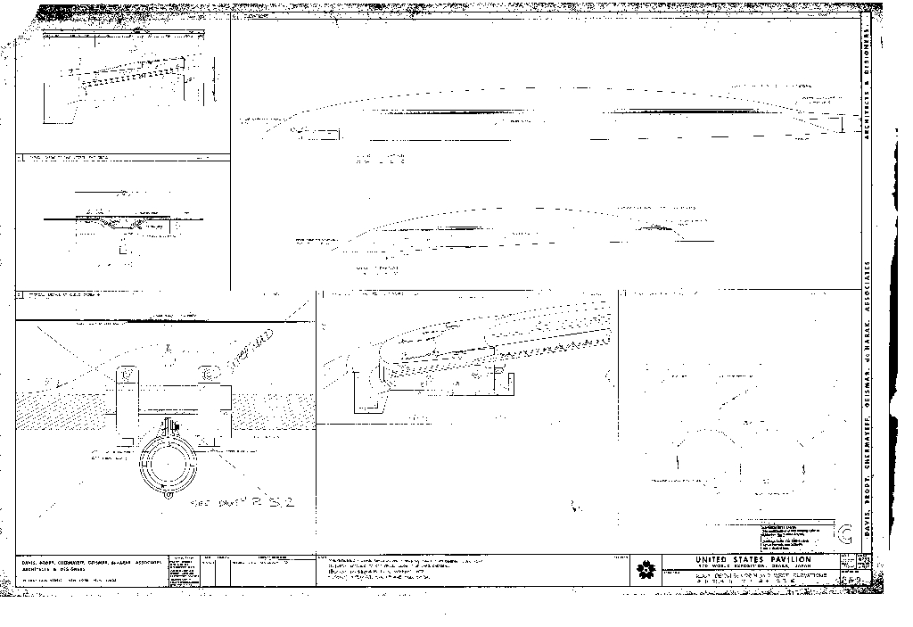 Roof Details, North and West Elevations
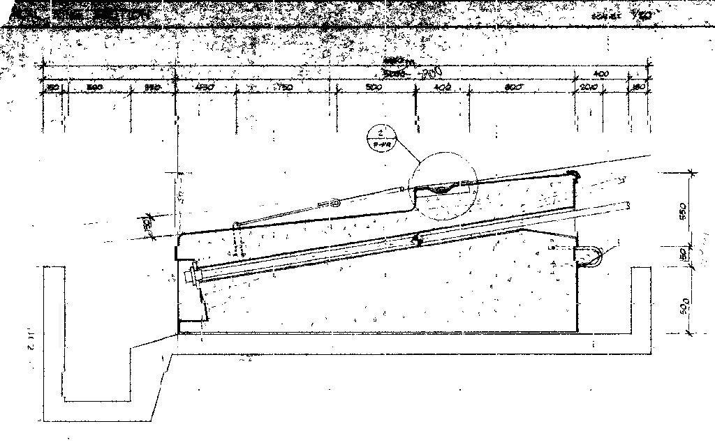 Typical Ring Sction
 Typical Fabric-To-Ring Attachment Detail
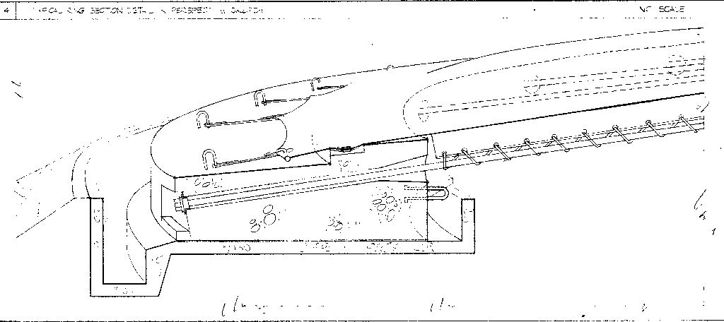 Typical Ring Section Detail in Perspective Sketch
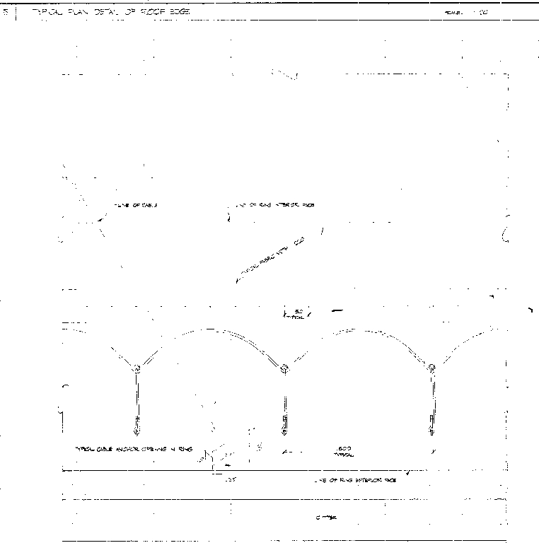 Typcial Plan Detail of Roof Edge
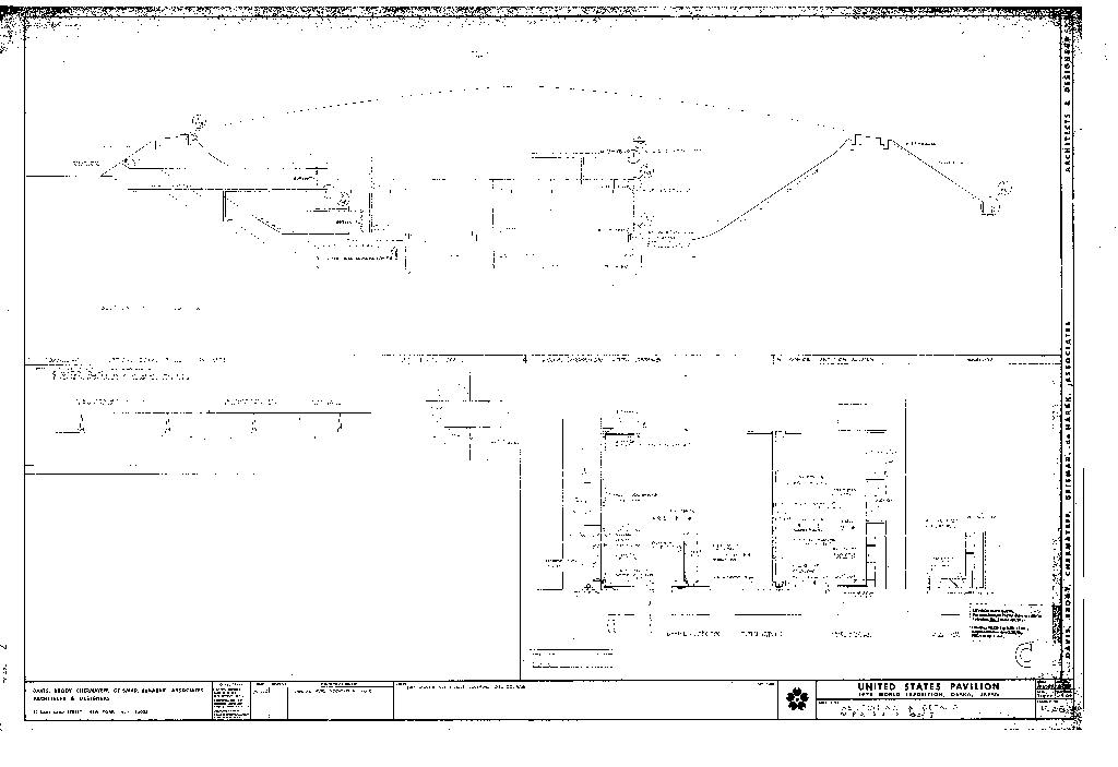 Section AA and Details
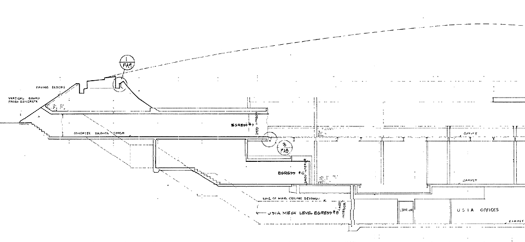 Section AA (left side of section)
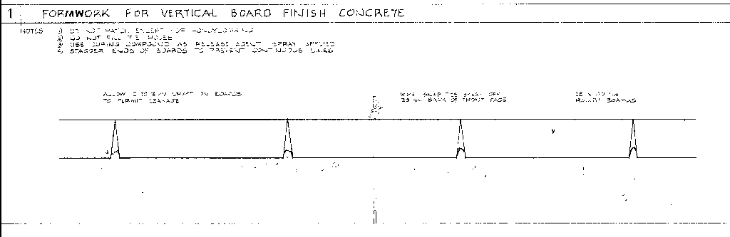 Formwork for Vertical Board Finish Core
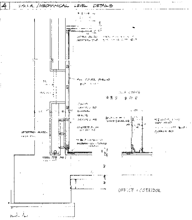 U.S.I.A./ Mechanical Level Details
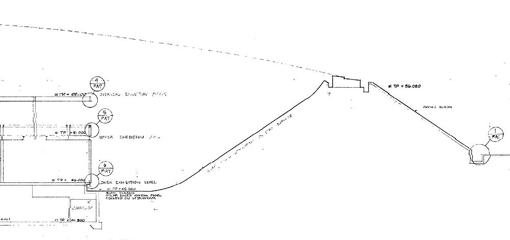 Section AA (right side of section)
 Site Plan
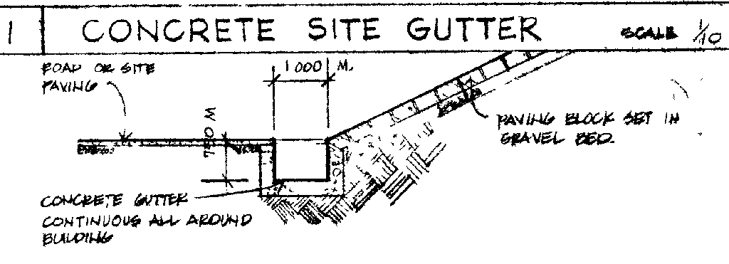 Concrete Site Gutter