The Infinitely Expandable Future of Air Structures
Architectural Forum, September 1970
Marguerite Villecco
The U.S. Pavilion at Expo 70, Osaka, Japan,
is the
subtlest and most surprising structure at the fair. It seems that
visitors can walk right through the columns that support every square
inch of its roof and never even notice.
The reason, of course, is that the columns are made of air. Though they
quite properly do the job that columns were intended to do - carry the
loads of the roof to the ground - they cannot be seen or felt.
Air structures are not new - either in concept or fact - but the Osaka
version is quite unlike any other ever attempted (see Dec. '69 issue).
It is the largest clear span, air-supported roof ever built, the
lightest (1 psf) roof of any material with this span and the first roof
with a superelliptical ring.
More important than the rightfully claimed firsts of this structure are
the structural and planning concepts it makes possible.
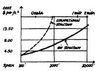
 The U.S. pavilion confirms the radical notion that the length and
breadth of a roof enclosure can be increased almost indefinitely with
only a small increase in the weight and cost per sq. ft. of its
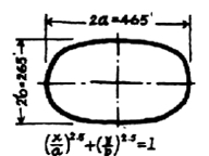
structural materials. The $2.6 million Osaka structure is 265 ft. wide
and 465 ft. long, yet according to its engineer, David Geiger, of New
York, the basic design could apply to a low-profile air structure of
almost any shape with an average diameter of one mile or greater.
The U.S. pavilion confirms the radical notion that the length and
breadth of a roof enclosure can be increased almost indefinitely with
only a small increase in the weight and cost per sq. ft. of its
structural materials. The $2.6 million Osaka structure is 265 ft. wide
and 465 ft. long, yet according to its engineer, David Geiger, of New
York, the basic design could apply to a low-profile air structure of
almost any shape with an average diameter of one mile or greater.
Earlier major structural innovations (such as the Galerie des Machines,
the Eiffel Tower, Brooklyn Bridge, hyperbolic paraboloid and thin shell)
have resulted in a highly visible and often startling change in physical
form. This innovation is an exception. Like the sophisticated
high-speed computer, its potential is not revealed by unusual physical
form. It is a structural revolution barely visible to the professional
and almost entirely invisible to the layman.
Its impact may nevertheless be extremely visible, for this structure
makes such schemes as totally enclosed urban areas believable and
feasible. Its architects, Davis, Brody & Associates, with designers
Chermayeff, Geismar, de Harak & Associates, of New York, envision entire
regions, states and even the lunar surface contained within low-profile
air structures.
Concept and structure
 The U.S. Pavilion has five primary components. The roof is made of a
translucent fiberglass fabric. The walls are formed by an earth
berm, which supports a concrete ring. The ring balances
the lateral loads of the cables which span the roof and is
superelliptical in shape. A system of blowers maintains internal
air pressure and so provides the air columns that support the roof.
The U.S. Pavilion has five primary components. The roof is made of a
translucent fiberglass fabric. The walls are formed by an earth
berm, which supports a concrete ring. The ring balances
the lateral loads of the cables which span the roof and is
superelliptical in shape. A system of blowers maintains internal
air pressure and so provides the air columns that support the roof.
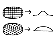
The superelliptical shape of the pavilion represents a relatively new
structural form. The super ellipse was formulated only 12 years ago and
published for the first time in 1959. The Osaka pavilion is a super
ellipse with an exponent of 2.5. If the exponent were 2, the shape would
be an ellipse. If it were to approach infinity, the shape would become
rectangular.
The fabric
The 100,000 sq. ft. roof of the pavilion is made of a translucent
closely woven fiberglass fabric that will withstand 700 lb. of stress
per inch of width. Because it is translucent, it admits light to the
pavilion interior by day and effects a luminous quality out of doors at
night. The cost of the roof,including cables and ring was $450,000, or
$4.50 per sq.ft.
Fiberglass has long been recognized for its great strength, but it has
not been popular as a structural material because it is brittle and
breaks easily. It works for the roof, however, because the designers
used a special small-diameter yarn fiber that compares to conventional
yarns as a sapling to an aging oak.
The National Aeronautics and Space Administration (NASA) sponsored the
yarn's development after the 1967 deaths of three astronauts by fire
demonstrated the need for a strong, flexible, fireproof material for
spacesuits. The resulting fiberglass yarn has a melting point of 1,000 F.
The fiberglass fabric had to be coated to reduce porosity and keep air
in, rain out. Also, fiberglass does not lend itself to sewing, so the
coating was necessary as a joining system for the pieces of fabric
(which were manufactured in the U.S., but assembled in Japan).
Vinyl was the coating selected for both sides of the fabric. It had to
be thick enough to transfer the stresses of the roof across the fabric
seams, so it and the fiberglass fabric are .03 in. thick. The seams
were bonded by heat and pressure.
Coatings are a problem that future designers will have to face anew.
Generally, a coating reduces the transparency of a fabric in proportion
to its thickness. The Osaka designers wanted a coating that would not
be opaque, yet offer longevity and high strength. Vinyl compromised the
long life requirement.
The pavilion may need a new roof membrane within ten years, which could
cost $300,000. The problem is that the vinyl deteriorates under
ultraviolet light, so will last only seven to ten years. (Neoprene
boasts a 20-year life, but is opaque.)
There are several possible solutions to the longevity problem. One
method is to have the fabric woven wide enough to span between cables,
perhaps 12 to 20 ft., and then joined to them by mechanical clamps. The
coating would then be applied only to reduce porosity, not to transfer
stress. Certain plastic films that will not deteriorate under
ultraviolet light and can be bonded to fiberglass could then be used as
a coating. This would allow a continuous maintenance program whereby
sections of coating could be removed, perhaps by solvent, and replaced.
Another scheme, proposed for the roof of a chilled water plant, is a
double skin system. The bottom layer, which would have cables attached,
could maintain internal pressure while the top layer was repaired or
replaced. The reverse is also true - the top layer could protect the
structure while men worked on the bottom layer.
New roof fabrics and coatings will soon be available to complement such
maintenance plans. For example, plastics are being improved so rapidly
that by the time the Osaka roof has to be replaced, the new membrane may
very likely be permanent.
The berm
The sides of the pavilion are a berm of earth scooped from inside the
pavilion and other soil added to improve compaction. The sloped sides
average about 20 feet in height and are covered with paving tiles outside
and with reflective plastic sheeting on the interior to mirror the roof
and sunlight.
A berm, however, is not necessary in a low-profile, air-inflated roof.
It nevertheless does its structural job very efficiently and
economically. It supports the concrete ring and deflects wind loads
upward so they create suction on the roof, thereby serving an
aerodynamic function that a vertical wall, for example, could not.
The U.S. pavilion, in fact, is the only kind of large space structure
that can be built on poor soil conditions, including fill, without pile
or caisson support. It required only 500 psf soil resistance, while six
to eight tons is normal. Even the 500 psf load resistance was required
only before the roof was inflated. Afterward, the columns of air
literally lift some of the weight of the concrete ring from the ground.
Davis-Brody already envisions a hollow, artificial berm system that
allows cars to park within it. They and Engineer David Geiger also look
to the time when our knowledge of thermal buoyancy (the principle that
hot air rises with sufficient force to carry a load) will permit the
walls to be removed altogether.
The ring
A concrete ring, 1,000 ft. long, 4 ft. high and 11.5 ft. wide, rests on
top of the earth berm, but is not fastened to it. The ring will resist
cable forces without bending under uniform loading of the roof.
Internal pressure and the dead load of the roof are examples of such
uniform loading.
Wind loading, however, comes from a single direction and is threrefore
assymetrical, so reinforcement against bending was necessary for this
load case.
A continuous slip joint, lined with two sheets of galvanized steel (one
bound to the ring, the other to the slab on the berm) separates the ring
from the berm. When loads cause the ring to move, the steel sheets
reduce friction enough so that the berm will not fail. Yet they provide
enough friction to prevent the ring from sliding off the berm under
seismic loading.
Such a slip joint may not be necessary in future applications, but it
was for the unprecendented Osaka effort. David Geiger explains: "The
prediction of the dynamic behavior of large, lightweight roofs is at the
edge of man's scientific knowledge. This roof is so light and has such
a large span that the damping mechanism was necessary as a safeguard.
But tests on this structure allow us to predict dynamic behavior more
accurately for future versions."
Wind tests conducted on a 1/100 dynamic model of the pavilion indicate
that under a uniform flow at the normal internal pressure of .03 psi,
there was no flutter at 200 mph winds. Under conditions of extreme wind
turbulence, there was a slight flutter at 131 mph, but this could be
controlled by increasing the air pressure inside. Thus the dynamic
respose of the structure is easily regulated by varying internal pressure.
Cable configuration
The ring is designed to take the place of concrete abutments and
perimeter cables, such as Frei Otto used on the German pavilion at Expo
67 (see April '67 issue). Vertical loads carried over a large span will
cause cable tensions, which increase with the shallowness of the roof
profile. An abutment or perimeter cable system will resist such force
through their mass, friction with the soil, or rock anchorage. (There
is, however, a certain lack of economy in burying too much of a structure.)
 A ring structure, on the other hand, balances those cable anchorage
forces within a closed system. Consequently, the earth bears only
vertical loads. The choice of a super ellipse for the Osaka pavilion
was an architectural decision, based in part on the architects' desire
to fully utilize the rectangular site.
A ring structure, on the other hand, balances those cable anchorage
forces within a closed system. Consequently, the earth bears only
vertical loads. The choice of a super ellipse for the Osaka pavilion
was an architectural decision, based in part on the architects' desire
to fully utilize the rectangular site.
Architects, however, need not think of ring shapes strictly in terms of
circles, ovals, ellipses or even super ellipses. While the choice
cannot be arbitrary, it can be quite varied.
According to David Geiger, it is governed by precisely determined
mathematical relationships between the ring configuration, cable
directions, and roof loading and shape.
In general, where the ring is flat, little roof load can be transferred
to it. Where the ring is more curved, it can carry more load.
The pavilion cables are common bridge strand, like that used in
suspension bridges, in three sizes: from 1-1/2" to 2-1/4" in
diameter. They are set on 20 foot centers in lengths ranging up to the
structure's long span of 465 feet. (For future and larger structures,
bridge strand can be obtained with a 4-in. diameter. Decreasing the
cable spacing also will increase load resistance.)
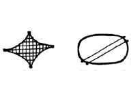
 The Osaka cable configuration was tried in several variations before the
design team decided to run the cables diagonally to the major axis of
the super ellipse. This decision saved materials, improved drainage and
also provided a better aerodynamic cross-section than alternative
configurations, such as radial cables with a central tension ring and
cables on a rectalinear grid, like a tennis racquet. The diagonal
pattern also required one-third less steel.
The Osaka cable configuration was tried in several variations before the
design team decided to run the cables diagonally to the major axis of
the super ellipse. This decision saved materials, improved drainage and
also provided a better aerodynamic cross-section than alternative
configurations, such as radial cables with a central tension ring and
cables on a rectalinear grid, like a tennis racquet. The diagonal
pattern also required one-third less steel.
The tension ring system was rejected because it would have involved
twice as many cable fittings, plus the cost of the ring itself. It
would have involved using the fabric inefficiently since it would have
to span wedge-shaped distances between the cables. The weight of the
tension ring could also have caused drainage problems by dimpling the
center of the roof.
The cable ends are fixed into sockets with zinc alloy filter and
anchored to the concrete ring. Their exact placement and points of
intersection were predetermined by a computer, then marked on the
individual cables. Details were developed at the ring and between the
fabric membrane and the cables to assure a uniform load on the fabric
and prevent concentrations of stress that could cause ripping. The
skirts between the cables and fabric membrane were attached by heat
seaming to the fabric then laced to the cables.
When the roof was inflated after all of the cable connections were made
on site, it behaved almost exactly as the engineers' calculations had
indicated they would. There was no need to make any adjustments in
either the cable tensions or intersection points after inflation.
Air pressure system
The difference between the interior and exterior pressure in the
pavilion is .03 psi, or 1/500 of an atmosphere. This differential is
only equivalent to that between the first and sixth floor of a
building. If the span of the structure were increased the pressure
might have to increase slightly, perhaps to .06 psi, but this
too would be barely noticeable.
The U.S. pavilion has six 5.5 kw blowers, each with an 8,000 cfm
capacity, to keep the roof inflated. Safeguards include an emergency
generator system. If the roof did collapse, the steel frame of the
exhibits would keep the roof above people's heads; the cables would also
prevent complete collapse.
Two of these blowers are sufficient to hold the roof up and compensate
for the pavilion's vent system for air exchange. Entry and exit is
through revolving doors, which provide a kind of air lock (as would
standard doors at either end of corridors).
If all six of the blowers were operating, they would compensate for a
30-ft. square opening in the middle roof. If a larger hole were
desired, more blowers could easily handle the job. (Such open spaces in
the roof have particular interest because nothing - not even rain or
snow - can fall through. The outblast is too strong - often 20 to 30 mph.)
The quantity of air required to support the roof is therefore
independent of volume and calculated only to compensate for air
leakage. Given normal air leakage and openings, such as vents and
doors,the operating costs of a blower system are comparable to air
conditioning costs.
Problem areas
When the Expo 70 design team began working on the pavilion, they soon
discovered that none of the basic assumptions that guide designers in
conventional building projects would apply to this one. No one had ever
built a cable net system like this one before.
In every case, the building's performance has confirmed their basic
theories. Nevertheless, there remains a general prejudice agaist using
air structures as permanent buildings and the doubts generally are
concerned with problems of longevity, vandlism and snow loading.
The question of longevity primarily concerns the roof fabric and coating
as discussed earlier. Vandalism, however, is a potential problem as
people obviously fear that someone could slit the roof and enter or
collapse it. One way of solving this would be to weave loose wire
strands into the roof fabric. Unstressed wires are difficult to cut -
they will bend around scissors, for example. The same wires could help
prevent accidental rips and be heated to melt snow. Further, a slit
would have to be tremendous to collapse the roof since tension tends to
pull it closed and blowers can compensate for large openings.
Wires are not the only solution to snow loading. The normal rise of hot
air in the pavilion is probably enough to melt all but very heavy
snowfalls and more heaters could be added. A roof held up by thermal
buoyancy would obviously already have a high concentration of heat just
under the roof. Snow could even be blown away through holes in the roof.
The low profile of the structure is a good solution to some other
problems. Economically, it saves on vertical transportation systems,
wind loading and foundation costs. In Japan, where structures are
commonly designed to resist 150-mph winds, the low profile is important
in removing the mass of the structure from the wind. In the case of
Osaka, the low silhouette even prompted officials to relax the 150-mph
requirements and specify only 125-mph wind resistance. A cable roof of
any kind can have a low profile, but an air-supported version has a
better aerodynamic cross-section.
The only limit to the low profile is that a minimum curvature is
necessary for drainage. The Osaka building has a 23 ft.-high curve over
a 265-ft. short span and it would be difficult to reduce this and
maintain proper drainage.
Planning frontiers
The city planning implications of an almost infinite structural
enclosure have been talked about by Buckminster Fuller and others for
years. But, unlike Fuller's domes, the Osaka structure uses air column
support and it alone can escape the physical law that as a span
increases linearly, strength must increase geometrically. In this
sense, the Osaka structure, for gravity loads, is really a no-span
phenomenon - each square inch of the roof has air column support, which
can be extended almost infinitely. The pavilion, therefore, brings us
close to the human dream of the city-scale enclosed environment for the
first time.
Air inflated structures are already used as greenhouses, sports arenas,
warehouses, tennis court and swimming pool covers, exhibit areas, silos
and to protect construction sites. Air structures may soon be used for
schools, air terminals, theaters and hospitals.
 An air structure the same size as the
U.S. Pavilion could contain a cultural center, playing field, or
shopping plaza. The roof membrane of the pavilion is anchored to a concrete ring
separated from an earth berm by two sheets of galvanized steel that form
a continuous slip joint.
An air structure the same size as the
U.S. Pavilion could contain a cultural center, playing field, or
shopping plaza. The roof membrane of the pavilion is anchored to a concrete ring
separated from an earth berm by two sheets of galvanized steel that form
a continuous slip joint.
Davis, Brody sees the air-inflated structure as a translucent lid that
could enclose an entire town or business center or cultural center. And
the dreams go much further than that. A mile square building could even
enclose a 40-story office skyscraper, though the architects prefer a
scheme of placing highrise buildings outside the perimeter of a mammoth
terrarium. The structure makes this possible because it creates an
outdoor daylight effect inside, yet can boast indoor climate control.
The air structure need not be constructed as a new building, but may be
installed on existing ones, such as stadiums, provided they can be
pressurized.
Davis, Brody notes that the open, relaxed, sheltered environments
created by a climate-controlling, light-transmitting dome might
encourage the virtues of small lively towns, which they feel have so
conspicuously ceased to exist. Not only towns, but civilizations.
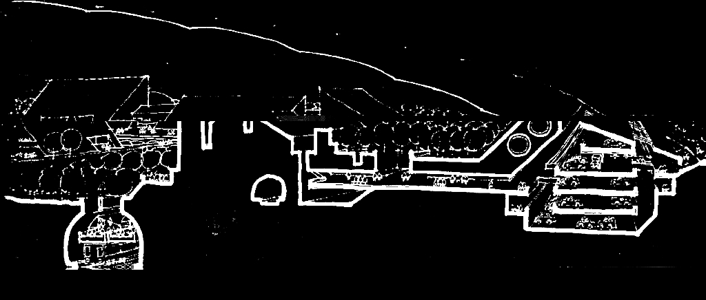
 The low-profile air structure can
be extended to a mile or more in span, when it could contain entire
towns, states, and regions.
The low-profile air structure can
be extended to a mile or more in span, when it could contain entire
towns, states, and regions.
Back to Osaka: Published Commentary
 An air structure the same size as the
U.S. Pavilion
An air structure the same size as the
U.S. Pavilion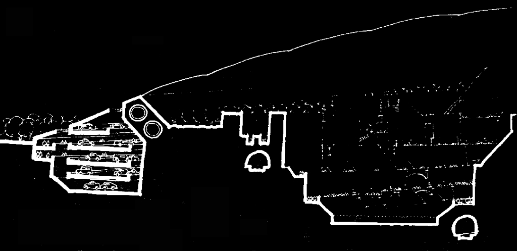
 The low-profile air structure