Low-Profile Air Structures in the USA
by David Geiger
Building Research and Practice, March / April 1975, p. 80-7.
Since the design of the United States Pavilion at Expo '70 in
Osaka, Japan, research in the United States has concentrated on
'permanent' incombustible fabrics permitting the classification of
low-profile air structures and tension structures as permanent buildings
within existing building codes. Five low-profile air structures built
to date or under construction are discussed in detail by Dr. Geiger, of
Geiger Berger Associates, New York.
At Expo 70 in Osaka, Japan, the United States built as its pavilion a
low-profile cable-restrained air structure weighing 59.7 N/m2 (1.25 lb
psf) and spanning 18.6 m x 138.0 m in plan. The design, fabrication,
construction and experimental testing of this structure has been fully
reported in the literature (ref. 1,2,3). The low cost, the aesthetic
quality of the clear-span translucent space and the confirmation of the
design theory through the experimental test results have led to the
extension of this structural system to other applications and to spans
up to 2400 m (8000 ft) in diameter.
(ref. 4)
 In extending this system beyond the US Pavilion design at Expo 70, it
was necessary to develop a fabric that was permanent and incombustible
so as to permit construction within existing United States building
codes. The resultant product was also self-cleaning, thus enabling
translucency to be maintained.
In extending this system beyond the US Pavilion design at Expo 70, it
was necessary to develop a fabric that was permanent and incombustible
so as to permit construction within existing United States building
codes. The resultant product was also self-cleaning, thus enabling
translucency to be maintained.
The material was developed under the sponsorship of the Educational
Facilities Laboratories. The final product consisted of Fiberglas
Fabric coated with Teflon Fluorocarbon Resin. The coating is a
formulated Teflon TFE and or FEP dispersion, which is applied after heat
cleaning and a first coat of silicone. The silicone coat prevents
wicking of water, which would cause the glass to deteriorate. To the
Teflon dispersion is added ten micronglass beads, which both lowers the
fabric cost and increases abrasion resistance. The strengths
[1]
of fabric
presently available vary from 200 lbs/in to 1000 lbs/in. For a 600
lbs/in fabric, the translucency can be made to vary from nearly opaque
to 18% translucent.
Under accelerated weathering conditions, where 300 hours in a
weatherometer is approximately equal to one year of real time
weathering, the fabric exhibits the following properties:
After 6000 hours of accelerated weathering (carbon arc) the subject
fabric showed no loss in strength.
Seamed samples of a 800 lb/in fabric have the ability to withstand
400 lb/in stress after 6000 hours accelerated weathering.
Trapezoidal Tear Strength showed a slight reduction after 2000 hours
accelerated weathering. (Tests were discontinued after 2000 hours due
to a limited sample.)
Fine testing
Tests are continuing. Fire tests on this material were performed for
the Owens-Corning Fiberglas Corporation. The test results are
summarized as follows:
1 ASTM E-84 tunnel test and 'Life Safety Code' NFPA-101 surface burning
characteristics:
| Flame spread | -5 |
Smoke developed | -5 |
Fuel contributed | -5 |
2 Standard Method of Test of Non-combustibility of Elementary Materials,
ASTM E-136-65:
- The material was rated 'non-combustible'. The recorded temperatures
of the interior and surface thermocouples did not at any time during the
test rise above the 750 degree C starting temperature of the furnace.
3 ASTM Specification E-108 and Underwriters' Laboratory Standard UL-790:
- This test contained three parts: A, Intermittent Flame Exposure
Test; B, Spread of Flame Test; and C, Burning Brand Test. The test
deviated from the standard procedure since the roof covering was
supported by a positive air pressure rather than the wooden decks
described in the ASTM Standard E-108 or UL-790. Pressure varied from
25.4 mm (1 in) of water at the beginning of the test and, because of
leaks, it reduced at times to 6.35 mm (.25 in) of water. Temperatures
reached were from 760 degrees C for Test A and B to 1204 degrees C for
Test C. The results indicated that this Teflon Coated Fiberglas
air-supported roof covering will satisfactorily withstand the three
methods of test in ASTM E-108 and UL-790 when tested for a Class B rating.
- For a non air-supported structures these identical tests were run
for a composite construction consisting of Teflon coated glass cloth and
50.8 mm (2 in) of Fiberglas flexible insulation with a white
vinyl-reinforced-foil vapor barrier facing. These test results also
established a Class B rating.
The straightness of the fibers in the warp direction accounts for the
linear stress strain curve which mirrors the physical properties of the
straight yarn. On the other hand, the fill fibers are kinked around
these and must straighten and consequently kink the warp fiber before
exhibiting the linear stress-strain characteristics of the base yarn.
For bi-axial loading, the stress strain characteristics are
non-linear,non-isotropic and vary according to previous stress history.
For fabric structures which are not cable reinforced it is necessary to
introduce the elastic properties of the fabric in the structural
analysis; while for cable-reinforced structures, the stiffness of the
fabric is negligible compared to that of the cables, and the cable
stiffness alone is used. The fabricator then accounts for the elastic
properties of the fabric in patterning and fabricating the individual panels.
 Interior of the U.S. Pavilion
Fabricated in rolls
The brittle characteristics of the glass fabric must be accounted for in
the basic design of the structure and the fabrication, packaging and
erection of the individual panels. It is preferred to deal with
fabricated material shipped to and handled at the site in rolls rather
than folded sheets. This is easily accomplished for the low-profile air
structures discussed herein. The fabric comes to the site in rolls from
9 m to 12 m (30 to 40 ft) wide and as long as 60 m (200 ft). The fabric
is clamped along its edges to the cables of the cable net. In those
cases where panels must be folded, it must be done by the fabricator
with care and handled in the field so that fracturing of the glass
fibers will not occur. The fabric used to date is made from beta yarn,
a 3.8 micrometre diameter filament, which is the smallest diameter and
consequently the most flexible fiber commercially available.
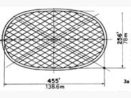
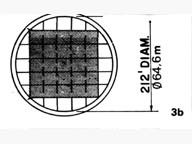
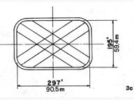
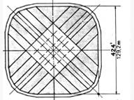
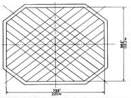
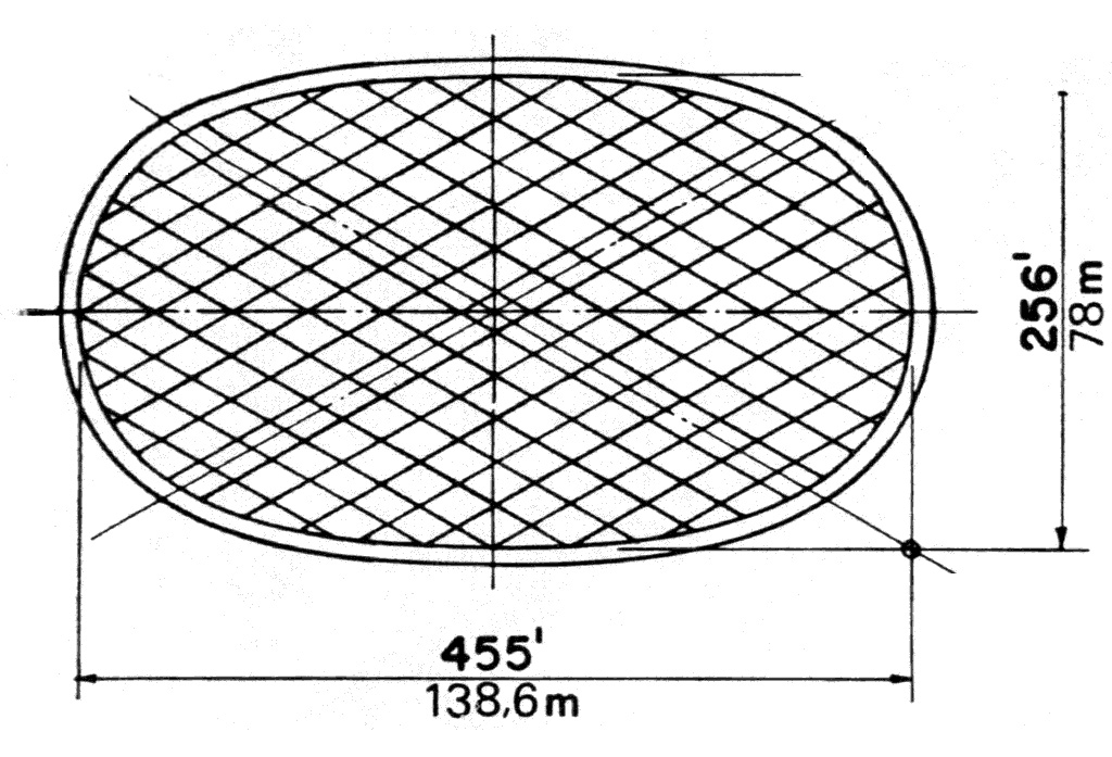
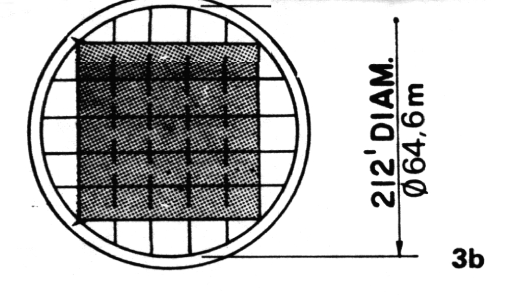
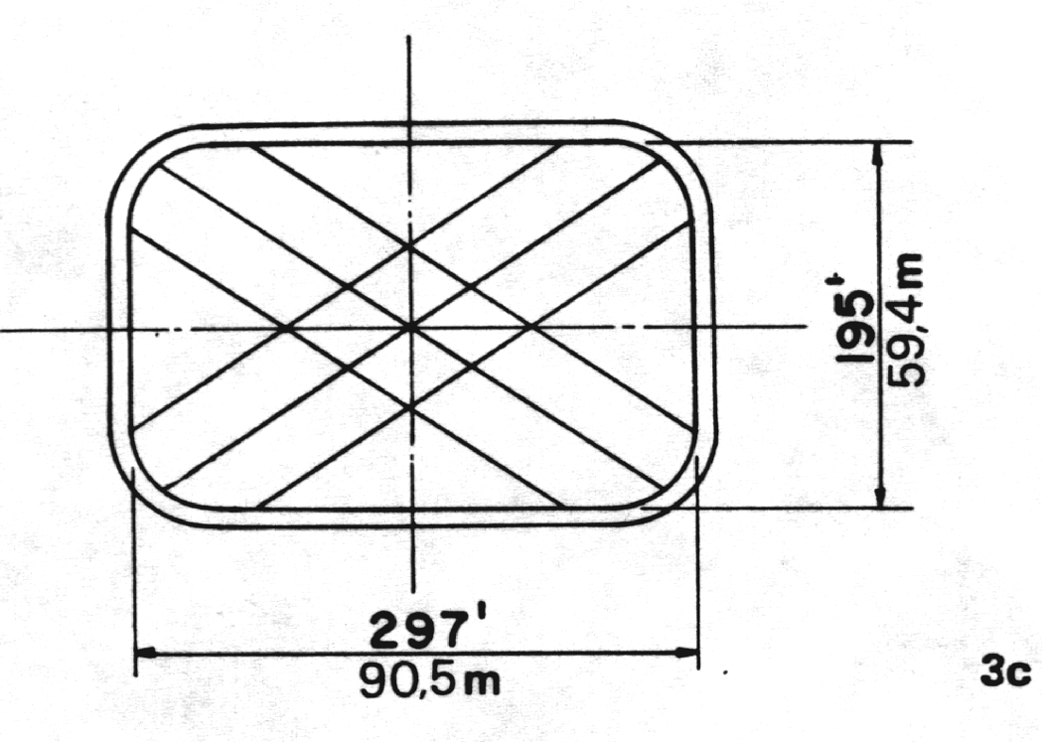
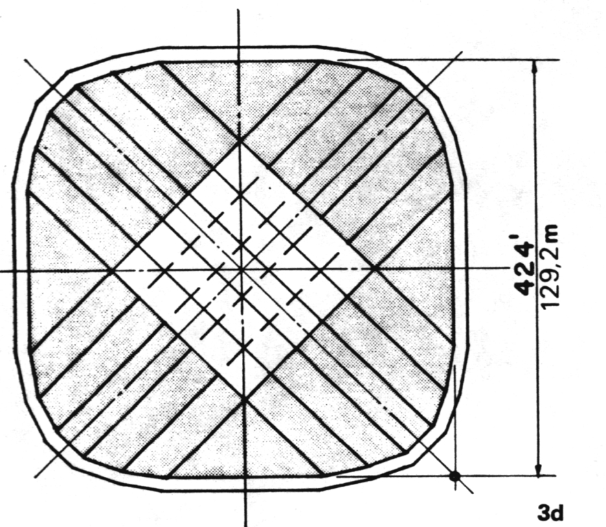
Illustrations show the various low-profile air structures that have
either been constructed or are under construction and which have been
designed by my firm. Shaded areas represent those where there exist two
layers of fabric for thermal and/or acoustic reasons. Cables,
represented by dashed lines, indicate those along which fabric is not
clamped. The principle of skewed
symmetry is embodied in United States Patents. This principle requires
that the cable directions be parallel to the diagonals of the
superscribed rectangle, so that the ring segments to which the cable
ends are anchored may, for a given roof load, be designed for zero
moment or for a minimum moment. Once the horizontal components have
been established from the conditions of minimum moment, the roof
ordinates are established for the given load case by solving a system of
simultaneous equations generated from conditions of vertical equilibrium
at each cable intersection. Under subsequent load cases, the cable net
distorts and the forces delivered to the compression ring introduce
larger moments which dictate the ring design.
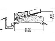
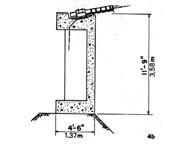
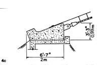
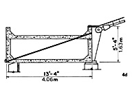
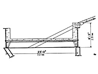
Figures 4a-4e show the ring cross sections corresponding
to the roofs shown. The ring shown in 4d also served as a mechanical
plenum and, for snow melting, hot air is introduced between the fabric
membranes. (The table summarizes information as to structural and
mechanical design and costs.)
| Location |
United States Pavilion
Osaka, Japan |
Milligan College
Johnson City, Tennessee |
Santa Clara University
Santa Clara, California |
Univ. of North Iowa
Cedar Falls, Iowa |
Pontiac Stadium
Pontiac, Michigan |
| Size (m) |
138.6 x 78.0 |
dia. 64.6 |
90.5 x 59.4 |
129.2 x 129.2 |
220.0 x 168.3 |
| Roof rise (m) |
7.0 |
4.8 |
7.2 |
14.6 |
15.2 |
| Cable spacing (m) |
6.0 |
9.0 |
12.0 |
12.9 |
12.6 |
| Cable thickness (dia) (mm) |
38.1 to 57.3 |
38.1 and two 27.0 |
47.6 |
73.0 |
79.4 |
| Fabric material |
vinyl glass single layer |
teflon glass double, insulated; also single |
teflon glass single |
teflon glass part double |
teflon glass single layer |
| Wind suction (in lbs/sq.ft.) |
30.0 |
15.0 |
12.0 |
12.9 |
12.6 |
| Wind suction (in N/sq. m.) |
1,464.6 |
732.3 |
585.9 |
732.3 |
732.3 |
| Snow load deflated (lbs/sq.ft) |
12.0 |
20.0 |
12.0 |
30.0 |
12.0 |
| Snow load deflated (N/sq.m) |
585.9 |
976.5 |
585.9 |
1,464.6 |
585.9 |
| Roof weight (in lbs/sq.ft) |
1.25 |
1.0 |
0.9 |
1.0 |
1.0 |
| Roof weight (in N/sq.m) |
61.0 |
48.8 |
43.9 |
48.8 |
48.8 |
| Blower capacity (cu.ft/min) |
120,000 |
130,000 |
400,000 |
370,000 |
3,500,000 |
| Blower capacity (cu.m/min) |
3,398 |
3,681 |
11,326 |
10,477 |
99,109 |
| Maximum no. of people |
3,398 |
3,681 |
11,326 |
10,477 |
99,109 |
| Roof translucency |
5,000 (6%) |
1,800 (0% and 14%) |
5,000 (14%) |
18,000 (11% average) |
80,000 (8% average) |
| Building costs |
|
|
|
|
|
| As bid (in US $/sq.ft) |
January 1969 |
March 1973 |
October 1973 |
July 1974 |
February 1974 |
| Ring cost |
50 |
1.77 |
1.20 |
2.89 |
4.00 |
| Roof cost |
4.00 |
6.60 |
6.47 |
9.07 |
7.27 |
| Total |
4.50 |
8.37 |
7.67 |
11.96 |
11.27 |
| HIVAC system |
5 |
4.25 |
7.27 |
2.92 |
3.19 |
| When inflated |
November 1969 |
October 1974 |
February 1975 |
July 1975 |
November 1975 |
For each of these structures the normal internal pressure is 4.5 lbs/f2
(215.1 N/m2). Under high winds only, suction is created on the roof
surface. Consequently, the internal pressure need not be increased for
dynamic stability. The maximum design wind velocity, to date, was 150
mph (240 kph) in Osaka, Japan. The low mass of the roof permits
construction in the most severe seismic zones without modification of
the design.
Snow loads up to 12 lb/ft2 (574 N/m2) may be carried by increasing the
internal pressure. Beyond this load snow must be melted since greater
internal pressures are impractical when one considers the design of
doors and exit wind velocities. In the event of failure of the snow
melting or pressurization system, the roof slowly deflates and hangs
free in the deflated positions.
The solar transmission properties of the roof fabric are summarized as
follows: (Table)
Because of the internal pressure, special care is used to reduce the
exfiltration and maintain airtightness. The horizontal expanse of earth
and structure under the nearly horizontal roof and the large volume of
air within the structure tend to moderate the swing of the day-night
cycle. Computer programs which model the above thermal properties
have enabled us to design mechanical systems with a lower first cost and
lower operating cost than conventional structures enclosing the same space.
It is our belief that future progress will be in the area of design,
where further developments in the membrane material and techniques for
changing the thermal properties will permit a considerable reduction in
the energy required for controlling the environment within the
encapsulated space.
[1]Editor's Footnote: Presumably tensile strength
according to standard textile industry tests on 2 inch strip of
material. A near equivalent commonly used internationally is kilogram
force per 5 cm (50 mm), expressed as 5 cm/kg. Thus 200lb/in = 180 kg 5
cm approx.
Back to text
References
1. D.H. Geiger, "US Pavilion at Expo '70 Features Air-Supported Cable Roof," Civil Engineering ASCE, March, 1970.
2. Y. Kida, N. Yamashita, and M. Takagi, "Experimental Reports of Air Structure (As the Pavilion of USA for the 1970 World Exposition). IASS Pacific Symposium - Part II on Tension Structures and Space Frames, October 17-23, 1971.
3. Y. Isono and Y. Nakahara, "Fabrication and Construction of US Pavilion Air Structure". IASS Pacific Symposium - Part II on Tension Structures and Space Frames, October 17-23, 1971.
4. "Air Fare" Progressive Architecture, August, 1972.
5. D.H. Geiger, Pneumatic Structures, Progressive Architecture, August,1972.
Back to Osaka: Published Commentary
 In extending this system beyond the US Pavilion design at Expo 70, it
was necessary to develop a fabric that was permanent and incombustible
so as to permit construction within existing United States building
codes. The resultant product was also self-cleaning, thus enabling
translucency to be maintained.
In extending this system beyond the US Pavilion design at Expo 70, it
was necessary to develop a fabric that was permanent and incombustible
so as to permit construction within existing United States building
codes. The resultant product was also self-cleaning, thus enabling
translucency to be maintained.  Interior of the U.S. Pavilion