 The Gymnastics and Fencing Arenas
(left to right)
Shells, Membranes and Space Frames, Proceedings IASS Symposium,
Osaka, 1986
David Geiger, Andrew Stefaniuk, and David Chen
Geiger Associates
R. Buckminster Fuller had previously defined the tensegrity dome as "islands of compression in a sea of tension" (1). Unfortunately, the sea of tension was configured as a triangulated net that prevented the realization of this structural system. Geiger Associates, through its long experience with tensile structures, realized that a flexible cable net could be made statically determinate for a given load case and that it would redistribute changes in load through changes in geometry. Thus, the cable dome was born (2).
The Gymnastics and Fencing Arenas
(left to right)
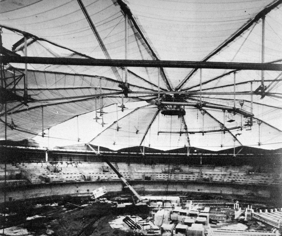 The Gymnastics Arena
Interior, Under Construction
The Gymnastic and the Fencing Arenas for the Korean Olympics are circular cable domes having diameters of 393 feet and 295 feet, respectively. The cable dome spans the space using continuous tension cables and discontinuous compression posts. Loads are carried from a central tension ring through a series of radial ridge cables, tension hoops, and intermediate diagonals until they are resolved in a perimeter compression ring. The tension hoops are 47.5 feet apart. For the Fencing Arena there are two tension hoops and for the Gymnastic Arena there are three. The ridge and diagonal cables separate the roof into sixteen equal segments. For roofs with equal segments, equal hoop spacing, equal loading on tributary areas and corresponding vertical geometry, the corresponding members of cable domes of different diameters carry the same load as one moves from the center of the dome outward. By analogy, the dome behaves as two cantilever trusses not quite touching at the center. This gives rise to significant repetition of details and allows for the use of castings at the connection points where posts and cables meet. As a consequence, the two rings of the Fencing Arena share the same castings at the top and bottom of the posts and the Gymnastics Arena requires another set of castings for the top and bottom of the posts of the outermost hoop.
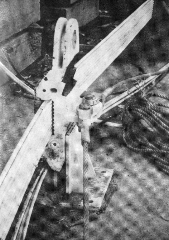 Lower Casting
with Hoop Cables
being spun at grade
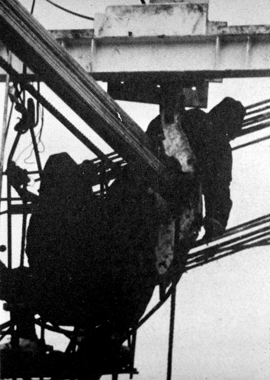 Lower Casting in place
Jacking of Diagonal Cables
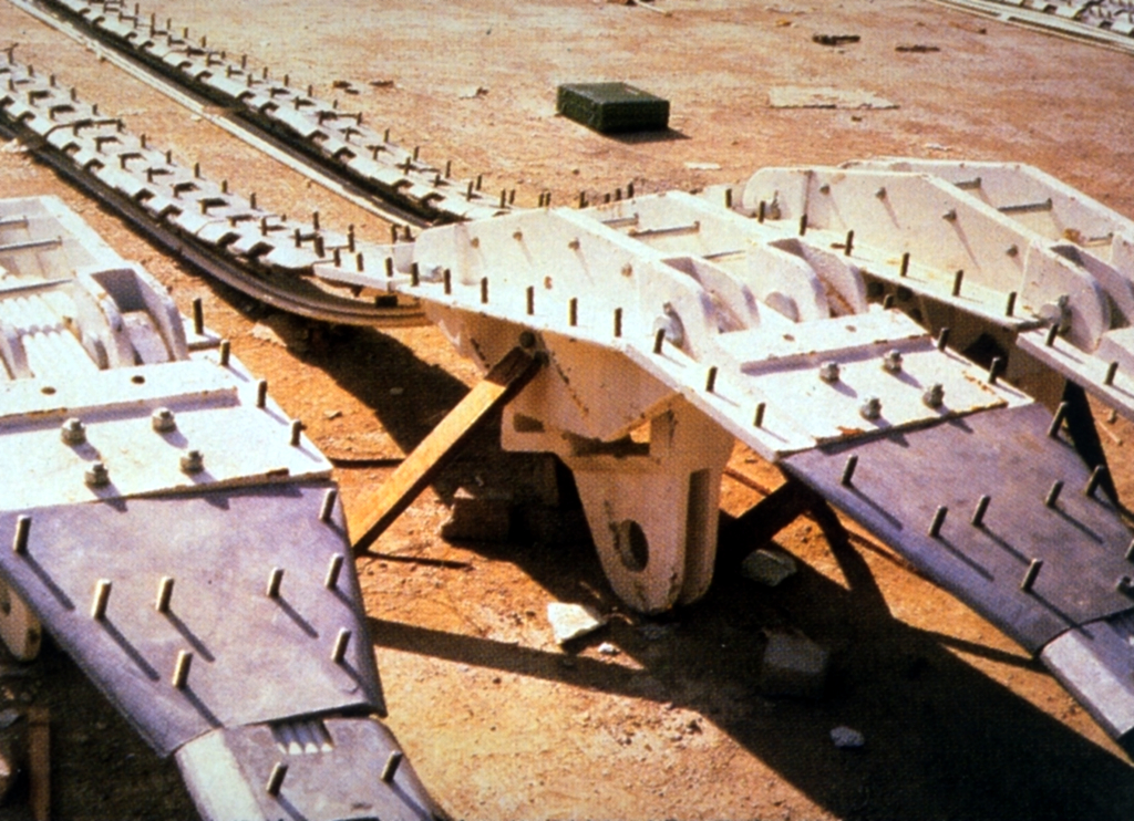 Upper Castings
and Ridge Cables
assembled at grade
The components of the roof consist primarily of continuous, parallel .6 inch diameter prestressing strand (ultimate capacity 58.6 kips) and metal castings. Bridge ropes with pinned sockets run between castings, control the geometry, and provide equilibrium at the castings based on the assumption that the greased prestressing strand continuous over the casting saddle has zero friction between it and the saddle. The elements are assembled at grade and are hoisted into a hanging position where they are jacked into final position using two hand-held jacks at the base of the posts of successive hoops.
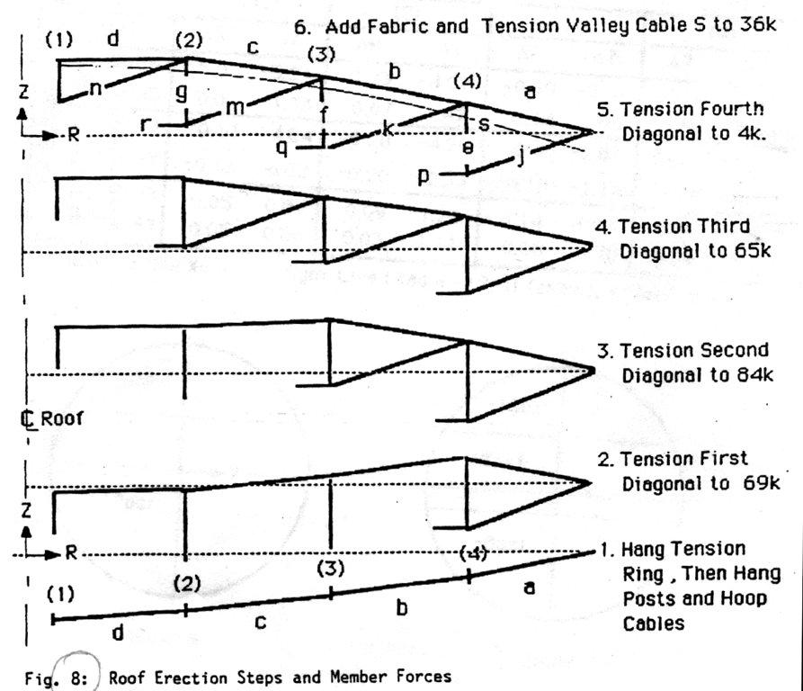 Roof Erection Steps
and Member Forces
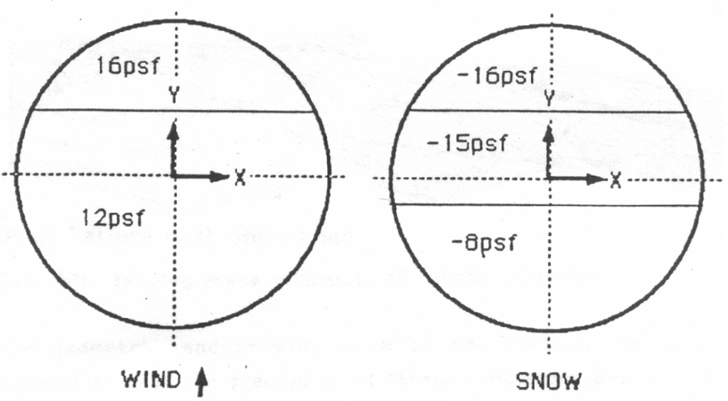 Non-Symetrical Live Load
lbs./sq.ft.
With the cables erected, the fabric is then deployed and clamped to the top of the ridge cables. Valley cables are prestressed (Step 6 - Table 1) thus inducing the required prestress into the fabric. The coordinates of the roof during the erection steps are given in Table II.
| Ridge Cable | Posts | Diagonal Cables | Hoop Cables | V.C. | ||||||||||||
|---|---|---|---|---|---|---|---|---|---|---|---|---|---|---|---|---|
| a | b | c | d | e | f | g | j | k | m | n | p | q | r | s | ||
| Erection Steps |
1 | 26 | 27 | 26 | 26 | - | - | - | - | - | - | - | - | - | - | - |
| 2 | 51 | 51 | 51 | 51 | 21 | - | - | 69 | - | - | - | 165 | - | - | - | |
| 3 | 177 | 31 | 88 | 88 | 45 | 24 | - | 137 | 84 | - | - | 352 | 202 | - | - | |
| 4 | 305 | 184 | 120 | 113 | 63 | 38 | 19 | 200 | 125 | 65 | - | 477 | 304 | 159 | - | |
| 5 | 306 | 184 | 120 | 116 | 70 | 39 | 19 | 201 | 126 | 66 | 4 | 479 | 305 | 160 | - | |
| 6 | 309 | 165 | 92 | 83 | 87 | 46 | 21 | 243 | 146 | 72 | 7 | 580 | 355 | 176 | 36 | |
| Snow | - | 382 | 154 | 55 | 32 | 155 | 73 | 27 | 426 | 221 | 87 | 18 | 1007 | 531 | 210 | 0 |
| Wind | - | 324 | 204 | 130 | 110 | 50 | 33 | 21 | 179 | 126 | 78 | 24 | 430 | 306 | 189 | 199 |
| (1) | (2) | (3) | (4) | ||||||
|---|---|---|---|---|---|---|---|---|---|
| R | Z | R | Z | R | Z | R | Z | ||
| Erection Steps |
1 | 8.20 | -22.36 | 54.33 | -20.85 | 105.20 | -15.99 | 152.53 | -7.45 |
| 2 | - | -2.52 | 54.38 | -1.30 | 105.36 | -2.70 | 152.38 | 3.67 | |
| 3 | - | 17.04 | 54.48 | 17.66 | 105.67 | 18.66 | 152.85 | 9.28 | |
| 4 | - | 23.90 | 54.53 | 24.36 | 105.31 | 17.53 | 152.72 | 8.92 | |
| 5 | - | 24.24 | 54.53 | 24.36 | 105.31 | 17.53 | 152.72 | 8.92 | |
| 6 | - | 23.03 | 54.46 | 23.46 | 105.23 | 16.70 | 152.67 | 8.70 | |
| (1) | (2) | (3) | (4) | ||||||
|---|---|---|---|---|---|---|---|---|---|
| R | Z | R | Z | R | Z | R | Z | ||
| Live Load |
Sym. Snow | 0.0 | -5.21 | -0.23 | -4.07 | -0.39 | -2.64 | -0.24 | -1.18 |
| Sym. Wind | 0.0 | 1.33 | 0.07 | 1.42 | 0.14 | 1.08 | 0.09 | 0.54 | |
| Non Sym. Snow +Y | 0.13 | 4.64 | -0.28 | 4.26 | -0.40 | -2.81 | -0.23 | -1.09 | |
| Non Sym. Snow -Y | -0.13 | -4.02 | -0.20 | -2.33 | -0.18 | -1.14 | -0.09 | -0.34 | |
| Non Sym. Wind +Y | 0.05 | 0.87 | 0.09 | 1.25 | 0.14 | 1.04 | 0.10 | 0.49 | |
| Non Sym. Wind -Y | -0.05 | 0.86 | 0.03 | 1.11 | 0.08 | 0.78 | 0.06 | 0.30 | |
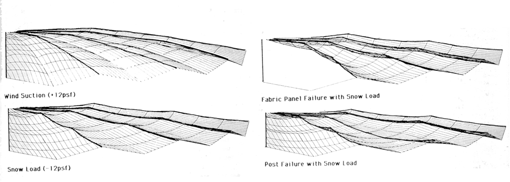 Fencing Arena
Computer Plots of Fabric Under Load
The structural behavior is highly nonlinear (Table III and Figure above). The cable, hoop, post structure, however, ts statically determinate for the snow load case tf the valley cable has zero load, this then becomes the initial configuratton. The behavior of the structure for other load cases ts determined by solving the nonlinear problem of the cable dome, fabric, and valley cable interaction for either changes in load or changes in structural configuration. Use of parallel cables builds in a redundancy that the authors feel is important to large span structures. The question remains as to the structural behavior in the event of failure of a fabric panel or a post. These problems were solved as well, and the results are shown in Figure 10. Structural details were configured to allow for the rotations accompanying these failure modes. A minimum factor of safety of 1.25 was maintained for these failure cases.
The cable dome may be built to a low rise, thus permitting the construction of very economical and lightweight domes. The domes in Korea, translucent and insulated to R10, weight about 3 psf and were constructed at a cost of approximately $20 per square foot. Other cable domes in design by Geiger Associates include the 256 by 304 foot superelliptical cable dome for the Illinois State University Arena, and the 680 foot diameter circular cable dome for the St. Petersburg Stadium (3). Neither the weight nor the cost increases significantly with increase in span or change from circular to superelliptical plan configuration.
1. Fuller, R. Buckminster (1983) INVENTIONS, THE PATENTED WORKS OF R. BUCKMENSTER FULLER. St. Martin's Press, New York
2. Tuckman, Janice and Shin Ho-Chul, "Olympic Domes First of Their Kin", ENGINEERING NEWS RECORD, March 6, 1986
3. "Cables, Pipes Lift Stadium Roof", ENGINEERING NEWS RECORD, March 1, 1984
4. Gobel, Martanne, "Dome a Forum of Controversy", CANADIAN BUILDING. Toronto, May 1984