 Section
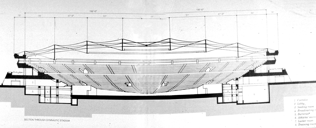
through gymnastic stadium
Architectural Record, September 1988
By Darl Rastorfer
Section
through gymnastic stadium
These roof structures, also known as tensegrity domes, are the first of their kind ever realized. The designer, engineer David H. Geiger, based his structural system on the theoretical work of R. Buckminster Fuller whose well-known fascination with tensile forces in nature led him to devote much of his later life to investigating man-made forms in which the presence of compression could be dramatically reduced and replaced by intricately connected networks of tension. He called such structural configurations "tensegrity," meaning tensional integrity, a phenomenon he described as compression elements becoming "small islands in a sea of tension."
Geiger was led to his re-evaluation of Fuller's pioneering work in the course of searching for a stadium roof enclosure that would be as economical as an air-supported structure while accommodating an insulated fabric membrane. The breakthrough that took theory into practice occurred when Geiger overcame the structural redundancies inherent in Fuller's triangulated configuration.
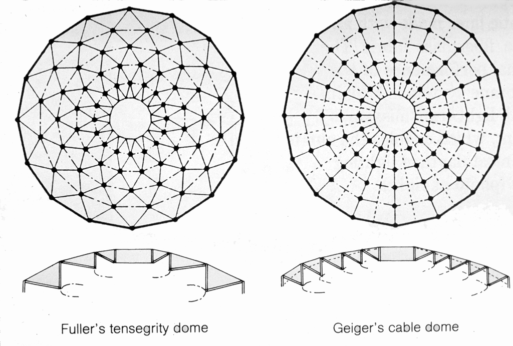 Comparison
of Fuller's and Geiger's tension domes
In Geiger's approach to tensegrity, continuous tension cables and discontinuous compression posts are laid out radially so that the three-dimensional flow of force is simplified, thereby making the cable dome statically determinant. With this configuration, low-profile curves are feasible, bringing with them the advantages of lower wind uplift; less drifting of snow, and therefore lower snow loads; and minimal surface area, thus reducing fabric costs. Since completing the domes in Seoul, Geiger has designed and is now overseeing construction of two other cable domes: a 256 by 304-ft elliptical dome at the University of Illinois, and a 680-ft-dia circular dome for the municipal stadium in St. Petersburg, Florida.
With this configuration, the dome behaves like a series of paired cantilever trusses not quite touching at the center. One of the system's advantages is that, as the length of span increases, the weight, 2 psf, remains constant and the cost per sq ft increases very little. All that is needed to accommodate increased spans is the addition of another module defined by its tension hoop. The Seoul gymnastic stadium's 390-ft-dia dome required three tension hoops set 47.5 ft apart. The 295-ft-dia dome over the fencing stadium required a two-hoop configuration.
The membrane that covers the dome comprises four independent layers. The outermost is a high-strength fiberglass fabric with a silicone coating on both sides. Beneath this is an 8-in. insulating layer of fine, silky fiberglass enclosed in polyester bags. Six inches beneath the insulation is a Mylar vapor barrier. Two feet below the Mylar is a silicone coated acoustic liner made with an open-weave, fiberglass fabric. The thermal performance of the membrane system is R10; its overall light transmission is 6 percent, which enables the sun to meet most daytime lighting needs.
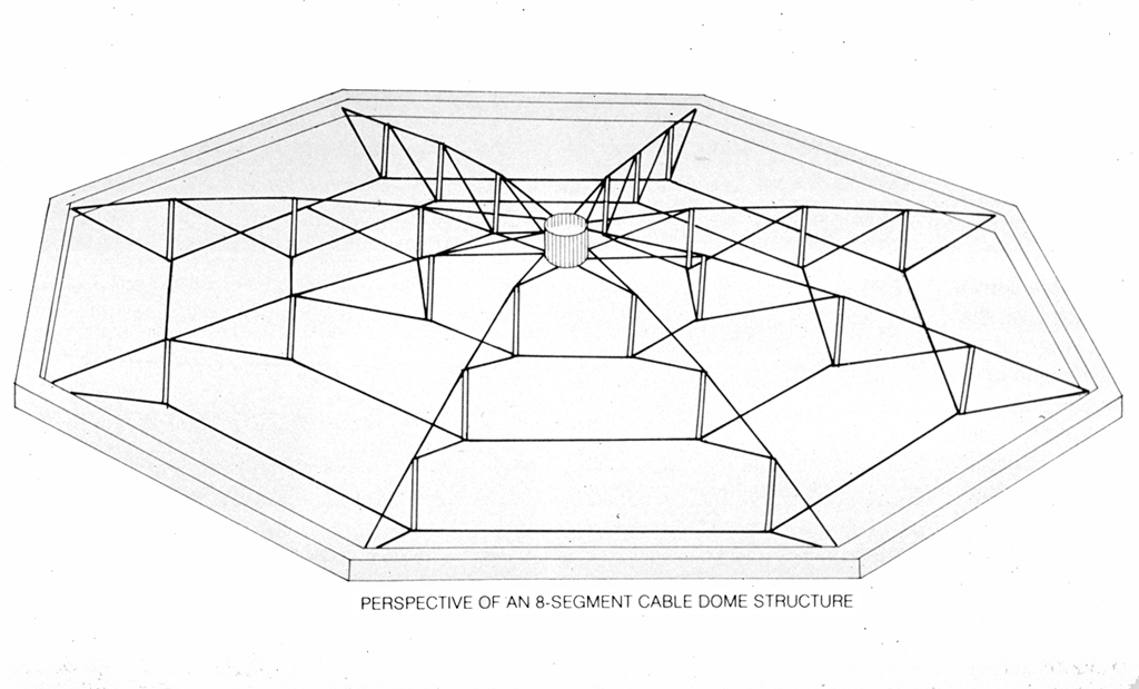 Perspective
of an 8-segment cable dome structure
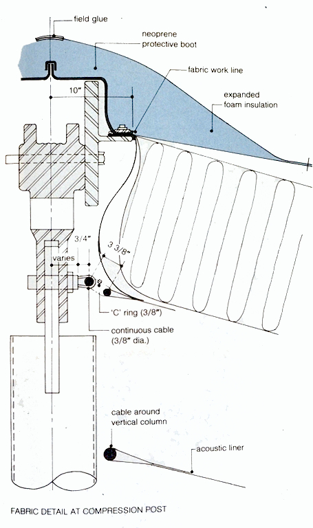 Fabric detail
at compression post
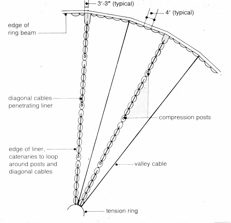 Partial reflected ceiling plan
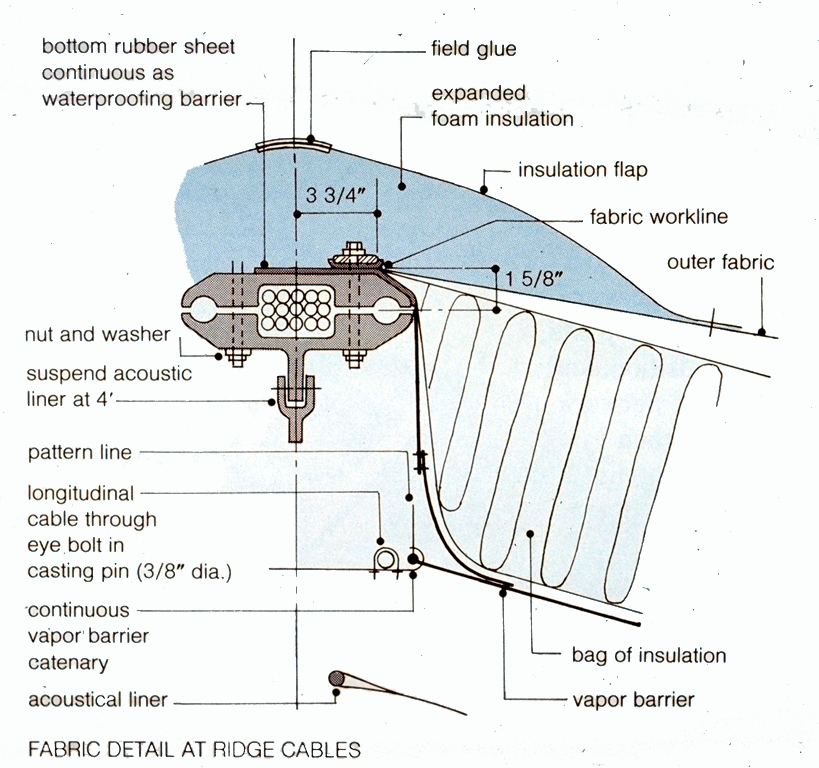 Fabric detail
at ridge cables
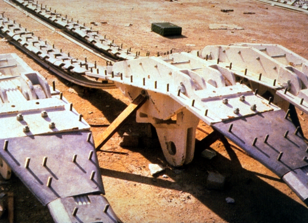 Construction of the cable domes began by laying in place, on the ground, the
tension ring and 16 ridge cables that are made by threading 0.6-in. steel
cable through the top casting for each compression post.
Construction of the cable domes began by laying in place, on the ground, the
tension ring and 16 ridge cables that are made by threading 0.6-in. steel
cable through the top casting for each compression post.
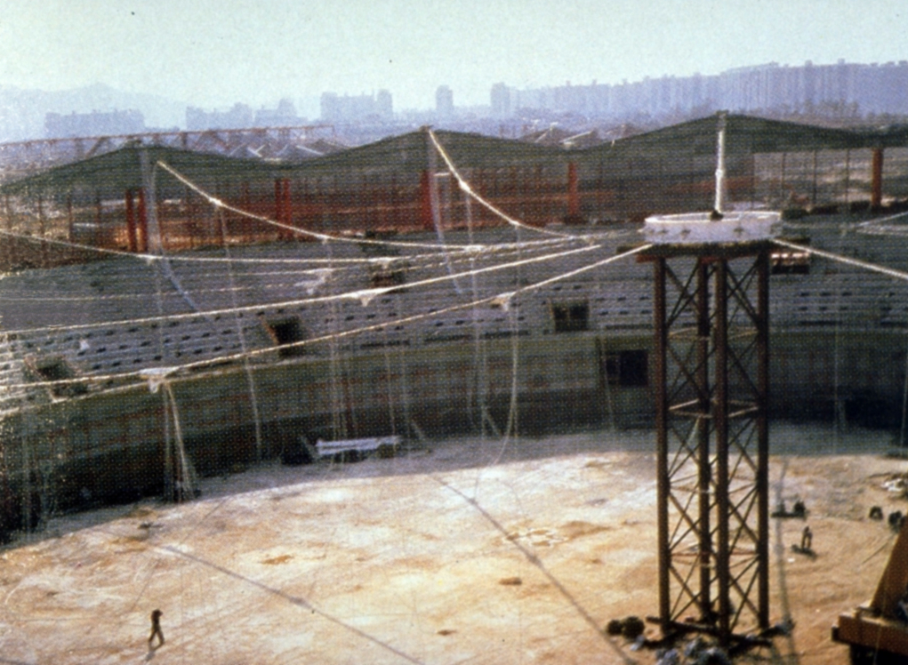 Although this assembly could have been lifted into place by tightening the
ridge cables at the compression ring, the erection subcontractors for the
stadium chose to lift the tension ring by crane to the top of a temporary
support tower.
Although this assembly could have been lifted into place by tightening the
ridge cables at the compression ring, the erection subcontractors for the
stadium chose to lift the tension ring by crane to the top of a temporary
support tower.
 With ridge cables spanning from the reinforced-concrete compression ring to
the supported tension ring, the strands of the outermost tension hoop were
laid in position on the ground with the bottom castings for the compression
posts in position. The bottoms of the posts themselves were then bolted to the
castings, and the hoop and posts were lifted and attached to the castings of
the already erected ridge cables.
With ridge cables spanning from the reinforced-concrete compression ring to
the supported tension ring, the strands of the outermost tension hoop were
laid in position on the ground with the bottom castings for the compression
posts in position. The bottoms of the posts themselves were then bolted to the
castings, and the hoop and posts were lifted and attached to the castings of
the already erected ridge cables.
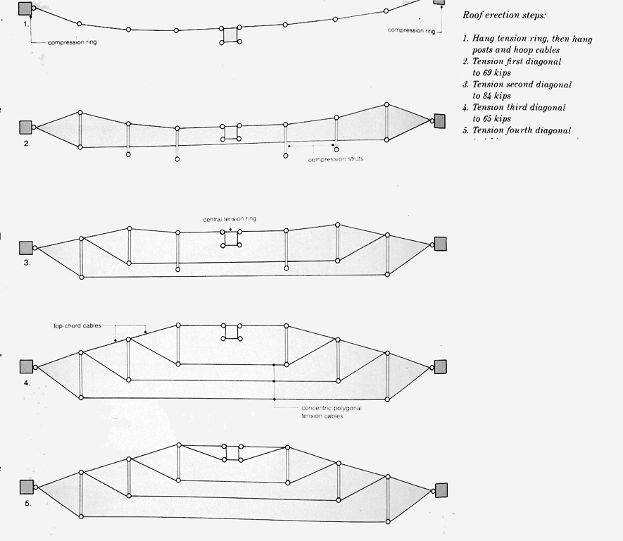 The two-strand diagonals, which run from the top of the compression ring to the bottom of
the posts, were then tensioned, pulling the hoop into final position (second
step in diagram sequence at left.) The process of laying out the hoop and
posts, lifting them into position, and lacing them into the network with
diagonals was then repeated for each hoop until the entire network was in place (third, fourth, and fifth steps in diagram).
The two-strand diagonals, which run from the top of the compression ring to the bottom of
the posts, were then tensioned, pulling the hoop into final position (second
step in diagram sequence at left.) The process of laying out the hoop and
posts, lifting them into position, and lacing them into the network with
diagonals was then repeated for each hoop until the entire network was in place (third, fourth, and fifth steps in diagram).
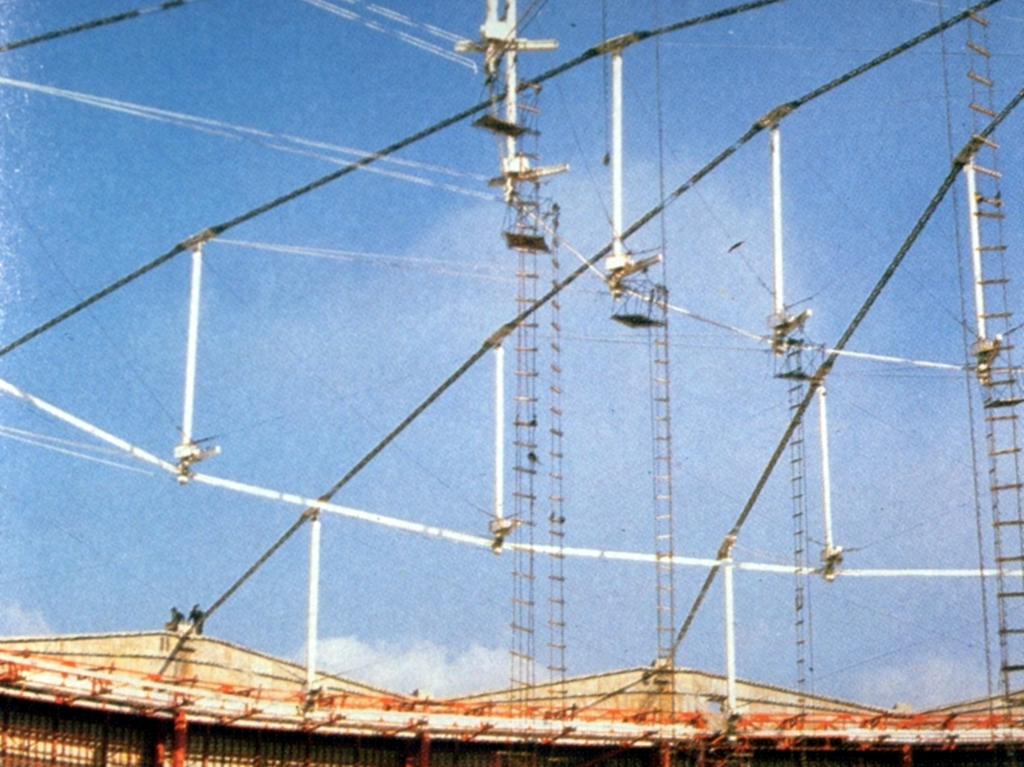 Thirty-two workers were stationed in baskets at the bottom of the compression posts to operate the jacks for tensioning the diagonals - two men at each of the 16 ridge cables. The workers
had to apply tension in perfect unison to raise the hoop to a level position.
Thirty-two workers were stationed in baskets at the bottom of the compression posts to operate the jacks for tensioning the diagonals - two men at each of the 16 ridge cables. The workers
had to apply tension in perfect unison to raise the hoop to a level position.
 This was the first layer to be installed in the four-layer system.
Starting from the tension ring, the layer was unfurled from a roller held
in position by a crane. Once unfurled, the fabric was bolted to the
castings with a stainless-steel nut. The casting to which the outer
layer was attached also has three attachment panels that match the three
layers of inner fabric - the top and bottom of the 8-in. insulation bag
and the vapor barrier below (these layers were installed from the
inside.) Finally, the acoustical liner was attached to the vapor barrier
with a zipper. With the four fabric layers in place, valley cables were
installed and tightened to stress the fabric.
This was the first layer to be installed in the four-layer system.
Starting from the tension ring, the layer was unfurled from a roller held
in position by a crane. Once unfurled, the fabric was bolted to the
castings with a stainless-steel nut. The casting to which the outer
layer was attached also has three attachment panels that match the three
layers of inner fabric - the top and bottom of the 8-in. insulation bag
and the vapor barrier below (these layers were installed from the
inside.) Finally, the acoustical liner was attached to the vapor barrier
with a zipper. With the four fabric layers in place, valley cables were
installed and tightened to stress the fabric.
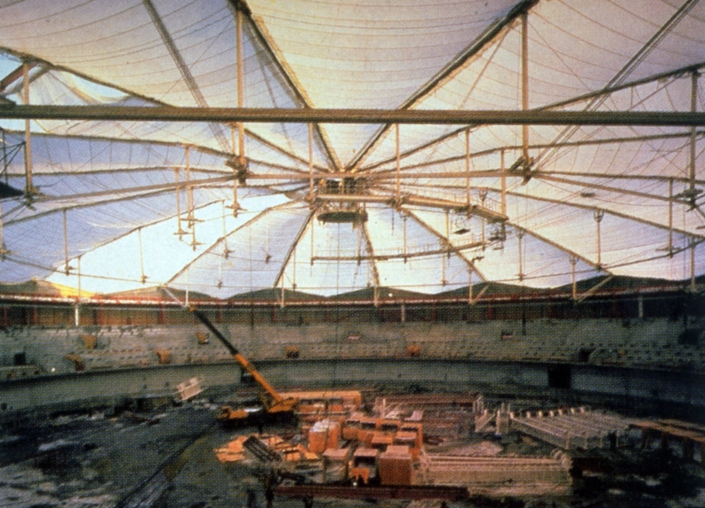
As a roofing system, the waterproofed fiberglass fabric must be carefully sealed at its construction seams. These seams occur at the 16 ridges that define the 16 fabric segments. Seams are formed with a silicone adhesive that requires no heat to effect a tight bond. At the points where the fabric is attached to the structure, silicone rubber gaskets were incorporated as water barrier. Expanded foam insulation and flaps of silicone-coated fiberglass fabric cover the gaskets and nuts. The outer lip compression ring, was sealed and flashed for water tightness. The lantern in the center of the dome, as illustrated in the photo of the fencing stadium, below, is part of the facility's ventilation system. Fans installed in, and vent it through the lantern.
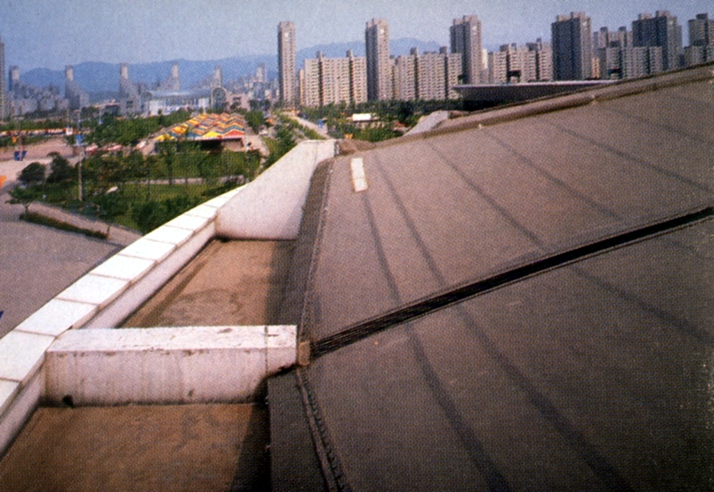 Outer lip of dome
which rests on compression ring
Gymnastic and fencing stadiums Seoul, South Korea
Architects:
Space Group of Korea (gymnastics stadium); Dong Myeong Architects and
Planners in join venture with Hong Ik University (fencing stadium)
Engineer:
Geiger, Gossen, Hamilton Engineers, PC (stadium domes) David H. Geiger,
principal-in-charge, Paul Gossen, project manager; David Chen, project
engineer/ computer operations
Contractors:
Ssang Yong Construction Co. Ltd.- (general contractor for gymnastics
stadium); Korea Shipbuilding & Engineering Co. (general contractor for
fencing stadium); Woo Chang Construction Co. (erection subcontractor for
gymnastics and fencing stadium domes)
 Roof section
 View of dome