| section A-A |
| section A-A |
|
Patscenter Princeton is a High-Tech building for a high-technology research facility and though
designed by British architects accommodates the constraints of the American building industry. So
it is a bit of a hybrid that makes a fascinating comparison with its predecessors. Peter Buchanan
introduces the scheme while Peter Rice of Ove Arup & Partners, the structural engineers
responsible, explains his design concerns.
|
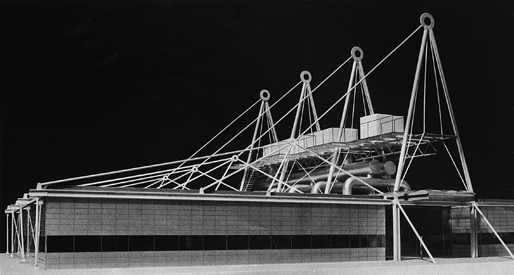
| model of three bays completed on one side only. Plant is suspended in cradels and unlike at Inmos external ducts are over the spine, and pierce its roof, only. |
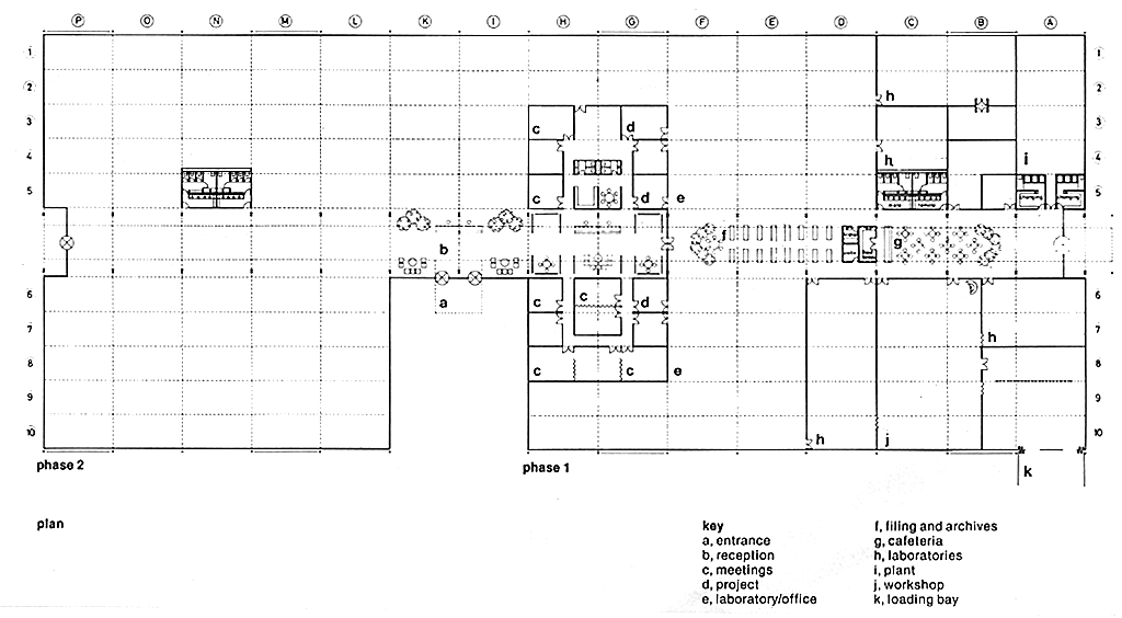
| plan |
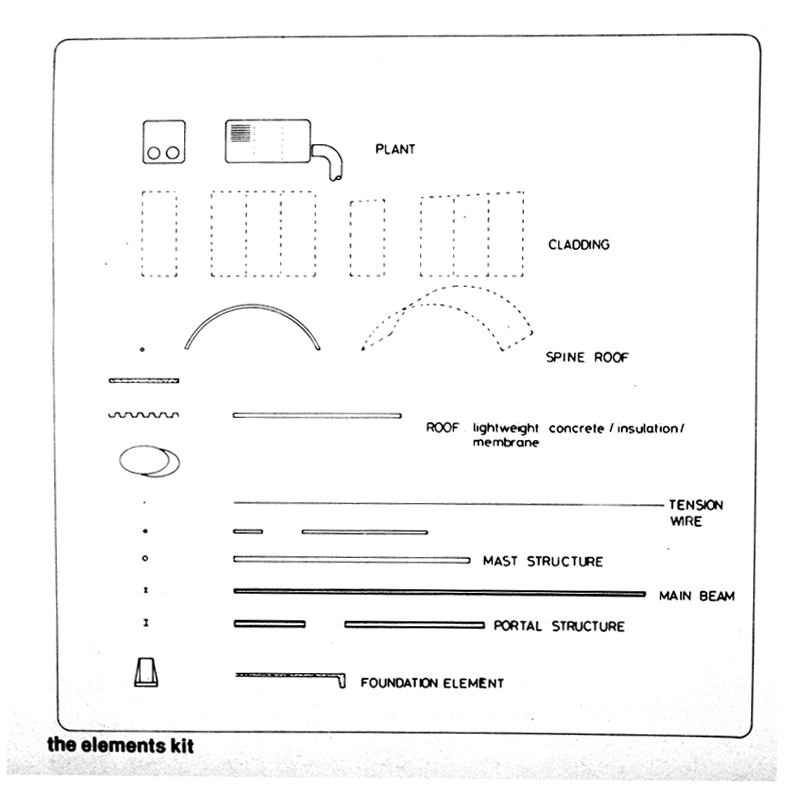
| the elements kit |
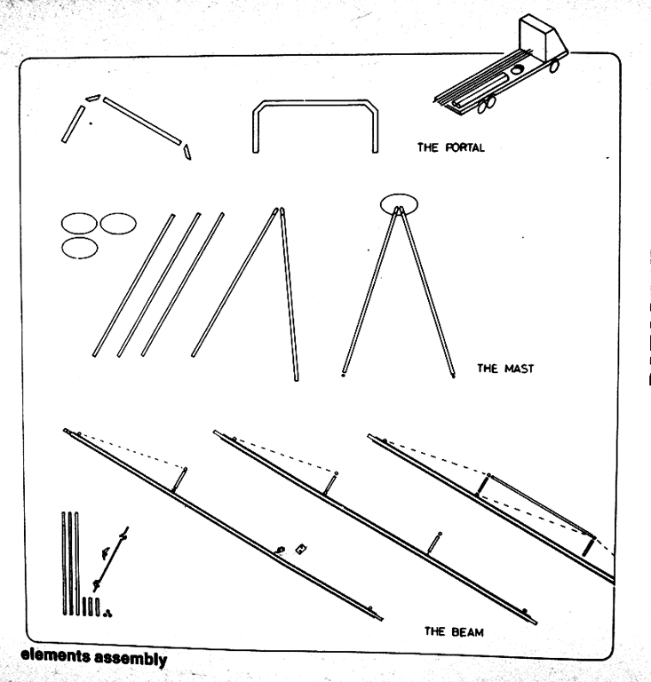
| elements assembly |
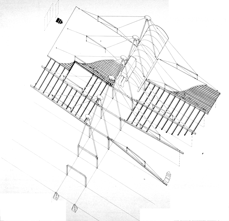
| early concept drawings of kit of parts, assembly sequence and completed building; suspension ties are now revised and vaulted roof to spine replaced by grid of dome lights |
The difference between these two structures reflects the different approaches of the two engineers as well as the very different realities of the American and British construction industries. The most obvious simplifications are that the filigreed lattice elements, the twin rows of cross-braced towers and the sleekly sculpted joints of Inmos are replaced by chunky industrial sections, the simplest of A-frames and bold circular joints. Trading delicacy of form for conceptual elegance, the smaller building has the more robust scale to its elements. It is obvious to the eye how each structural element works, the beams being clearly suspended with none of the slight ambiguities of Inmos where gently sagging ties to the quite big lattice trusses suggest the latter as self-supporting. Unlike Inmos the plant sits exposed, not in boxes, and on suspended cradles not on cross beams. So in many ways the concepts, and especially the 'feel' of the structure is closer to Rice's structure for the Fleetguard factory at Quimper than it is to the Inmos structure.
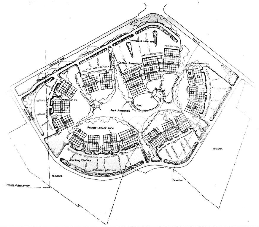
| Richard Rogers & Partners' proposed site plan for 50-acre industrial park |
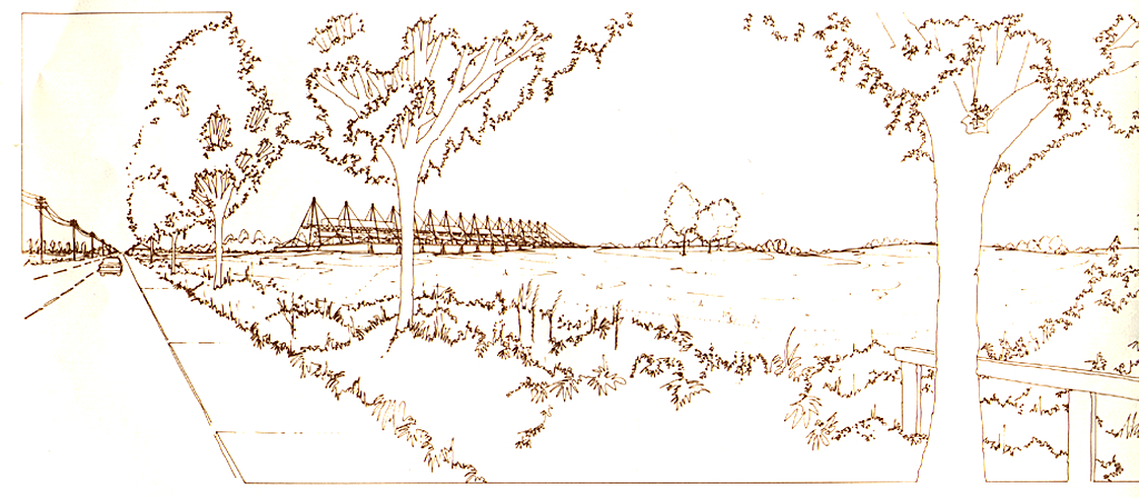
| phases 1 and 2 viewed from afar |
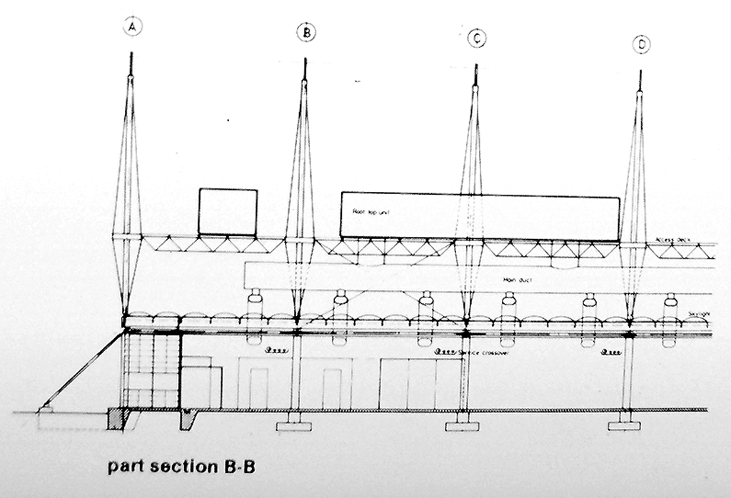
| part section B-B |
The research and development work done at Patscenter is constantly changing, requiring a more fluid plan Ulan at Inmos. With only two rows of I-section columns interrupting the plan, the spine is handled quite differently. It is not a sealed route running through the building, but is sometimes open to the flexible laboratory/office space that makes up most of the accommodation. In the spine are various communal facilities such as archives and recreation so that 'if the spine at Inmos was a street for movement, at Patscenter it is more of an elongated piazza' as Pierre Botschi says. His only regret is that the clear vaulted roof which would have given it the generous feel of a galleria has had to be replaced by a grid of domelights which contrast less spectacularly with the office areas. While only a horizontal strip is glazed and so transparent, the whole external wall admits light, being clad with a proprietary translucent panel. All told, there is a conceptual and formal economy to the design that is not only convincing, but also has a certain ease in its matter-of-factness.
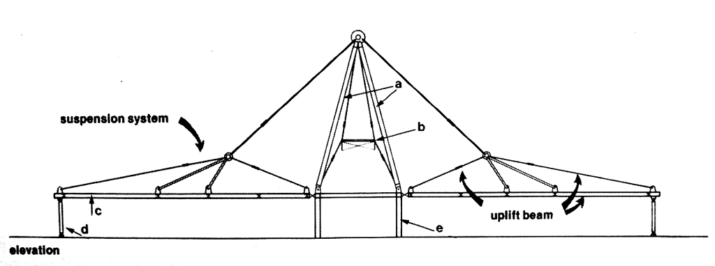
The principle of a central support with large free spaces on either side was established after early discussions with the architect. The structural frame has four separate elements. These are the tension support element, which consists of a compression A-frame with hangers supporting a horizontal roof beam on either side. This horizontal roof beam spans 25 m and the suspension system is placed at 9 m centres. The A-frame sits on the second element, which is a portal frame designed to resist the horizontal load and the vertical asymmetric load transmitted to it by the A-frame. The third component in the system is the tie-down columns which support the two suspended beams and resist uplift. These beams will themselves resist uplift under wind load through the tension support members and the beam acting together as an uplift beam. The fourth component is the suspended platforms for the services capsules and the longitundinal bracing. The structural solution attempted to achieve four aims:
1 All the horizontal forces associated with the vertical support system are resolved at roof level. This means that only the external horizontal loads (wind loads) are transferred to ground level, and this is done through the central portal, so there is the minimum interruption to flow of space across the centre of the plan. This is all that is required even when vertical loads on one side {such as drifting snow loads) give large asymmetric horizontal forces in upper triangular frame.
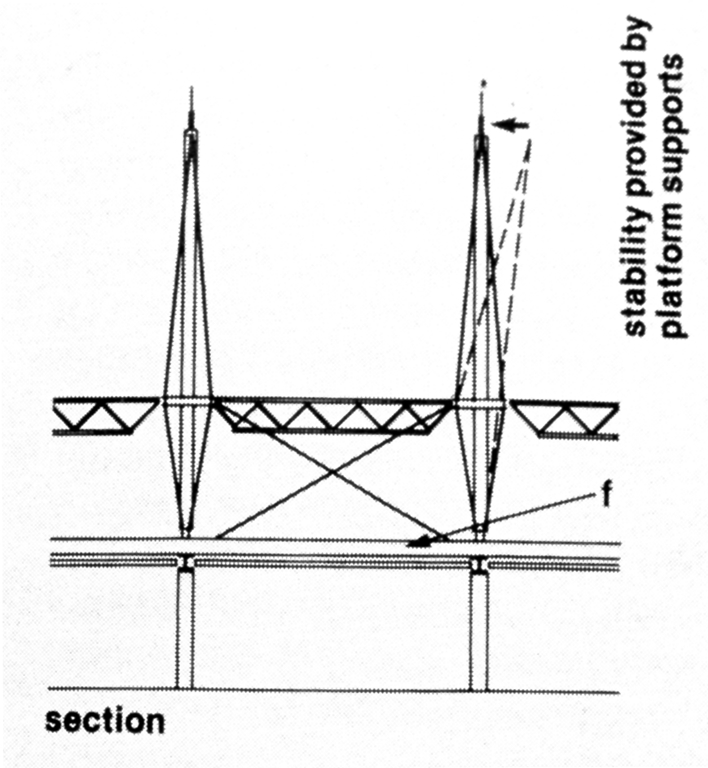
| section |
2 The uplift loads of wind are separately catered for to ensure that the roof would be truly lightweight. The uplift beam and the suspension system work together.
| elevation |
3 The stability of the support frame normal to its plane avoids direct stabilising members to the ground. The stability is provided by ensuring that the way the compression members of the A-frame rotate out of plane produces restoring forces on the frame.
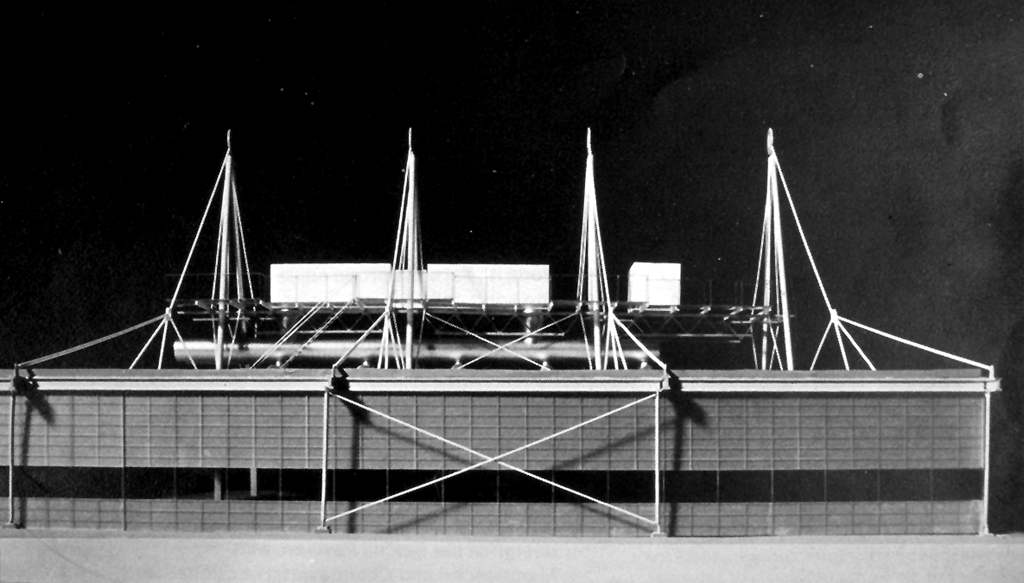
| side elevation of model of three bays. |
4 The bulk of the steel weight is in standard steel construction, with only some special visible external elements being designed in non- conventional rods and pin-ended columns. This is important in the environment of the American construction industry which penalises non- conventional construction heavily.
The early sketches did not have the suspended plant room capsules. This meant that although the A-frame was basically stable geometrically, it felt unsafe visually. By using the hangers of suspended platforms to stabilise top of the A-frame, the frame was stiffened, and the assembly felt visually more stable.
Also in the early sketches of the tension support system, a symmetrical arrangement of supports was used. It was found in the detailed analysis that these did not remain in tension in all load cases. To solve this the geometry was changed to that which is now to be built.
 Back to The PatCenter Main Menu