 Figure 2.
Introduction
Patscenter is a new research facility for PA Technology on the outskirts of Princeton, a university
town which is close to the American eastern seaboard and approximately mid-way between New
York and Washington. Early in 1982, management and technology consultants, PA Technology,
were seeking to rationalize their American operations and while doing so gain a more distinctive
image. They chose to achieve this by appointing the architect Richard Rogers to provide them
with a laboratory and corporate facility with the potential for easy growth. Richard Rogers invited
us to assist in the development of the building brief, planning and scheme design; providing both
structural and building services engineering input.
Architects and consulting engineers require a state licence to practice in the USA. Neither ourselves nor Richard Rogers had the appropriate licences for the State of New Jersey and, as non-residents, we were not eligible to apply for them. For the architect this was overcome by Richard Rogers & Partners working in association with a small firm of New Jersey architects. For ourselves it was established that we should hand over the project to separate structural and building services engineers in New York once the scheme design and project budget had been approved by the client. Our involvement was therefore to end with the American engineers' acceptance of our scheme design.
The success of a building such as Patscenter with its highly expressed structure and services is very dependent on the quality and consistency of their detailing. This was recognized in our brief, which was extended beyond the basic scheme design to include the development in principle of the key engineering details.
Building layout and concept
The nature of the research projects which PA Technology are appointed to carry out varies
considerably. Their work involves both desk-based studies and practical experimentation; both
office areas and laboratories are therefore required. However, the mix of spaces and the layout of
rooms needs to be adaptable to enable different combinations of research commissions to be
undertaken.
Other less flexible areas are also required. Early during the briefing stage, specific areas were scheduled for central administration offices, computing, library, reception and conference facilities.
This combination of flexible research space and less flexible central facilities, together with the client's expressed desire that the building form should be readily extendable, determined the concept for the building's internal planning. The central facilities are located in a 9.0m wide spine which also duplicates as the principal circulation zone. On either side of this spine two large single storey enclosures, each 72m long x 22.5m wide, provide the research space. To achieve the required flexibility these research areas are organized on a 9.Om x 4.5m planning grid and are column-free. All vertical structure is Contained within the central spine, or is external to the building envelope.
The desired layouts of offices and laboratories have been formed by erecting free-standing demountable enclosures within the completed building. These subdivide the two large research spaces into combinations of rooms, generally using the discipline of the planning grid.
The resulting building plan is essentially linear with a dominant symmetry about the spine (Fig. 1). From the outset the architect was keen that this should be reflected in the building form. Richard Rogers felt that the building should be perceived as a series of slices, each representing a one bay module. Further slices could thus be added at a later date without impairing the concept and visual integrity of the building.
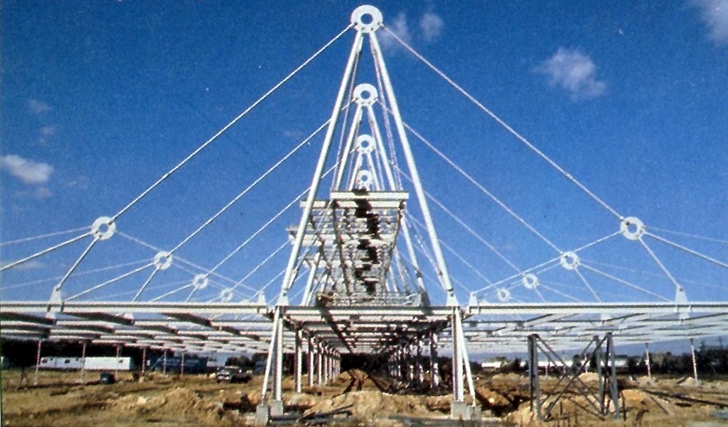
| New structure being assembled. (photo:Ram Ahronov, Project Architect) |
| View of central spine. (Photo: Otto Baitz) |
The structure is externally expressed to achieve the column-free research enclosures and, equally importantly, to provide the main architectural theme for the building. The large single-storey building, with its general roof level only 4.5m above ground level, is enlivened by the deliberately dramatic steelwork frame (Fig. 2). Major services plant is suspended above the central spine keeping it clear of the main building envelope. The building services also, therefore, contribute to the architectural image (Figs. 3 and 4).
Structural frame
The structure comprises a row of nine identical frames spaced at 9.0m intervals along the
building length. Each frame has a stiff 7.5m wide portal within the central spine, above which
extends a rigid 15m high bipod mast. Inclined tension members splay out symmetrically from
the top of this mast to provide mid-span support for the main roof beams over the research
enclosures.
| Evolution of structural frame. |
Whilst the geometry of the bipod masts and their supporting portal was established early in the project, it took longer for the geometry of the tension system to be developed (Fig. 5). From the start we requested that the suspension system must incorporate a truss to resist wind uplift, and thus avoid the inefficiency of having to ballast the roof down with sufficient dead weight to maintain always a net downwards loading. The initial scheme (Fig. 5a) had twinned inclined hangers on each side of the mast connecting to the roof system at 1/3 span points. This was originally based on clear roof spans of 27m. However, for the 24m roof spans which emerged from the internal planning, this arrangement was considered over-elaborate and the outer hangers were found to be making very little contribution to the roof support.
A hanger with an inclination to the horizontal of less than about 30� does little to prevent vertical deflection of the roof and, at such a small inclination, the hanger tends to sag visibly under its own weight. Its axial stiffness, initially at any rate, is therefore that of a shallow catenary rather than a direct tension member. Also, with a central mast arrangement such as the Patscenter building, the horizontal component arising from the inclined hangers is resolved at roof level by the primary roof beams carrying compression forces back to the stiff spine. The outer hangers of small inclination tended to put an unacceptably high compression component into the main roof beams.
In scaling down the roof suspension system to one which seemed more appropriate for the 24m spans the outer hangers were removed (Fig. 5b). However, the very clear and symmetrical arrangement for the wind uplift truss over each roof span, which was liked by the architects at this stage, caused us further problems.
We approached this new geometry by first convincing ourselves that even with pinned joints at the main roof beam suspension points, the system was not a mechanism- it would have been absurd to have the whole stayed-roof system dependent on the bending stiffness of the primary beams. Assessing whether a structure containing a high proportion of tension-only members is statically determinate is not always immediately obvious. We chose the simple graphical method of plotting the loci of node displacements for rigid sub-assemblies and then assessing whether the omitted tension members would have had to increase in length to follow these loci (Fig. 6). If a displacement locus was possible with all omitted tension members either maintaining or reducing their original length, then the system would clearly be a mechanism.
Although the system was not a mechanism it proved highly inefficient. To prevent lateral displacement of node C much of the tension in member AC had to continue as a tension in member CF. This both reduced the vertical upward reaction available at node C to take the roof loadings and put large compression loads into the roof beam at node F. Also member BC could only be prevented from going slack by enormously pre-tensioning member CF (Fig. 7a). Again since further tension in member CF resulted in increased compression in the roof beam, this would have been counter-productive.
Inclining the central triangle CDE simultaneously solved all of these problems (Fig. 7b) and provided the final as-built geometry (Fig. 5c). The main hanger became more steeply inclined, thus beneficially reducing its horizontal component. The resultant line of action of members CD and CE fell within the enclosed triangle ABC, automatically keeping member BC taut. It also became possible to minimize the bending moments induced in the primary roof beam by initially setting the resultant of CD and CE just within the line of AC. Fine tuning is then achieved by controlling tension in member CF to pull the resultant further round.
The uplift wind truss, although possibly less clearly stated, is still provided by this final geometry. Members CD and CE are required to act as compression struts when there is a net uplift loading, but their lengths have not been greatly increased relative to the previous geometry. They therefore remain as sufficiently slender tubes for the overall tensile effect of the suspension system to prevail. In fact, the tensile effect tends to be enhanced by the asymmetry of triangle CDE with the system looking more taut, and the various members all appearing to have been drawn upwards towards the masthead.
Mast stability
Longitudinal stability of the row of nine bipod masts is provided indirectly by making use of the
suspended services plant platforms and their support hangers. This has enabled the structure,
when viewed from the side elevation, to appear relatively simple and uncluttered. The masts
project upwards at 9.0m centres independently of one another, conveying the image of the
building being segmental with a bay-by-bay add-on flexibility (Fig. 8).
| Side View of building at night (Photo: Otto Baitz) |
Out of plane loadings on the masts and suspension systems are transmitted down to the main roof level via the structural chassis of the services platforms. All horizontal forces associated with the vertical support systems are then resolved at roof level and transferred to ground level through the combination of central portals and diagonal bracing at the ends and sides of the building.
This solution for the longitudinal stability was not immediately arrived at. We started by proposing diagonal cross-bracing between the masts along the building length, but the architects were keen to preserve the planarity of the main roof suspension systems. They would not accept longitudinal members connecting to the bipod masts; at least not above the services plant where they could be seen. We did not want to introduce restraint at low level to the bipod masts since this would introduce bending stresses and compromise their behaviour as simple axial struts.
An apparently unrelated design decision solved our dilemma. The architects decided to light naturally the central spine with a skylight and to do this the roof-mounted services were raised clear of the roof onto services platforms, continuous along the length of the building. It was obvious that these platforms should be suspended from the bipod masts since they further justified the need for the masts. This was done using hangers from the mastheads. Cross-bracing the services platforms down to the main roof level would prevent them from displacing longitudinally, and we realized that they could thus be used to stabilize indirectly the masts.
If the platform support hangers were in the same vertical plane as the bipod mast a stable equilibrium system resulted (Fig. 9a). As the mast rotated under the influence of out of plane loading a restoring force was mobilized by the change in geometry of the system. Although the system had no initial stiffness, the rate of gain of lateral stiffness was rapid. We decided to anticipate this gain and by presetting the platform support hangers at relatively slender angles to the bipod mast, obtained the final mast geometry (Figs. 9b and 10).
Interestingly, therefore, whilst the services platforms are held in place by the bipod masts, it is these same platforms which prevent the masts from toppling over. Without the building services plant there would be no requirement for the platforms and hence no mast stability system. Thus the building services help to justify the structure and vice versa. Also at no point do the horizontal platforms connect directly to the bipod members. This is emphasized in the completed building by the different colour paint finishes, to maintain the visual clarity of the simple bipod masts transmitting the building's weight down towards the ground.
Construction details
The bulk of the steel weight is in standard rolled I-sections, with oniy some special visible
external elements being designed in nonconventional rods and pin-ended columns. However, the
rods, hollow section columns and even the clevises and turnbuckles were selected from the
American Institute of Steel Construction standard products. This was important in the
environment of the American construction industry which penalizes non-conventional
construction heavily. The only elements uniquely made for the project are the annular node
plates. These were chosen to avoid complex castings and to enable the standard clevises to be
used at the ends of all tension rods. During the scheme design, we proposed that joint instability at
the mast heads should be overcome by the use of twin bolts for the bipod connections (Fig. 11).
However, this detail was later improved by using one large bolt which can be seen and one small
bolt which cannot (Fig. 12). Tension rods were selected in preference to cables because of their
higher modulus of elasticity and because they were easier to paint.
| Centreline view of mast structure (Photo: Otto Baitz) |
A lightweight metal decking roof is supported by secondary beams at 4.5m centres, which span between the main roof beams. These main beams are below the roof and are continuous over their 24m length. Profiled lug plates welded to the top of the main beams project through the roof deck to connect to the external suspension system (Fig. 11). The overall weight of structural steelwork equates to about 45kg/m^2.
The building floor is a simple power-floated ground slab, with a local perimeter thickening and other internal longitudinal thickenings to accommodate underfloor piped services channels. In certain areas a flush floor trunking is set into the floor on a regular grid. Pad foundations bearing on undisturbed natural sands are used for the main structure.
Cladding
New buildings are required to have cladding envelopes which satisfy criteria relating to energy
efficiency, as defined by the American ASHRAE 90/75 code. These relate to thermal
transmission, light transmission and solar gains; with certain trade-offs permitted between roof
and walls depending on their particular characteristics.
The architects were keen for the perimeter wall cladding to contain as much glazing as possible, and we undertook energy and daylight studies to identify the scope for realistic trade-offs. For various walling systems, with different combinations of glazed area and insulation performance, the studies identified the required performance of the roof insulation.
We were also concerned that large glazing areas would constitute a glare source with unacceptable contrast levels between perimeter and interior zones of the research enclosures. Overhang shading studies were therefore undertaken (Fig. 13).
| Shading study of SW elevation |
A successful compromise was reached by the use of a Kalwall translucent cladding system. This proprietary system comprises a sandwich panel formed by bonding two specially formulated, light transmitting, fibreglass sheets to either side of an interlocked aluminium grid frame. For maximum light transmission the gap between the sheets is left empty. To increase the thermal insulation the gap is filled with special inserts of translucent fibreglass. These inserts are fitted within the aluminium grid frame and their density is selected to achieve the required insulation and light transmission. The overall panel thickness is 70mm. Panels arrived on site set into 1.5m wide modular frames of full storey height.
Whilst the introduction of the central spine skylight helped the structural design it further complicated the building envelope analysis. Studies were done to assess the shading provided by the external ducts to establish a preferred arrangement for ducts and skylight, and the energy trade-offs between walls and roof were reassessed. The Kalwall specification was set accordingly; providing 20% clear glazing area with the remaining area having a 17% light transmission and a 1.3W/m2�C U-value. From inside the building the overall effect is somewhat akin to that of the Japanese paper screen (Figs. 14 and 15).
| General Interior view of research enclosure, prior to casting ground slab or insta\llation of services, showing column-free interior and translucence of Kalwall cladding. (Photo: Ram\ Ahronov) |
The following services are provided:
Air-conditioning
Ventilation
Fume hood exhaust
Industrial hood exhaust
Compressed air
Towns gas
Hot water
Cold water
Heating
Electrical power busbar and trunking
Communication trunking
Foul drainage
Surface water drainage
Laboratory waste drainage
Heat detectors
Fire alarms
Sprinklers
Lighting
External lighting
Emergency lighting
Lightning protection
Lateral feeders running internally at high level provide the secondary distribution into the research enclosures. In these areas an integrated zoning strategy has been evolved for the services and building(Fig. 17). Such a strategy determines a fixed zone or route for each service or band of services, with none being allowed into another's zone. It ensures that all services will in fact fit into the building, standardizes installation details, and greatly assists maintenance.
The very rigid discipline which this zoning strategy imposes might be thought to inhibit adaptability. However, the reverse is true. By applying the same zoning strategy throughout the building a space is allocated for every service in each planning module. This is the case whether or not all of the services are initially installed in every module. Therefore, if the usage of an area is changed and in consequence requires a previously omitted service to be installed, then this is always possible because a distribution philosophy and route already exists for the service.
One further advantage of the zoning strategy is that the rigid discipline makes it possible for the services to be expressed. It was known from the start that the engineering services were to contribute to the architectural image of the building, both inside and out. Without precise control over the locations of all services it was unlikely that they would be visually acceptable.
HVAC
The building is air-conditioned by a variable volume system using fan-assisted terminal units.
Generally one fan terminal unit is provided to serve two 9.0m x 4.5m planning modules in the
internal areas, and one terminal per module in the spine and perimeter areas. Two central
packaged air-handling units incorporating acoustic treatment, fans, humidification, filtration,
direct expansion cooling and direct gas-fired heating are located above the spine. The two
airhandling units connect to common circular supply and extract ducts suspended below the
air-handling plant platforms. Connections are taken off the primary distribution ducts into the
building (Figs. 18 and 19).
Ventilation is provided to toilets by separate roof-mounted fan units, and similarly, industrial exhaust hoods when required are connected to individual extract fans on the roof interlinked with the VAV terminals.
Supplementary heating is provided by perimeter baseboard and skylight finned tube elements, with fan heaters in the loading bay. Heated water is distributed from a central gas-fired boiler plant.
Piped services
With the exception of the drainage systems, the piped services are distributed at high level with
lateral feeders from the primary spine distribution. Cold water is distributed at mains pressure
and hot water from a central storage cylinder located in the ground floor plant room. Industrial
quality compressed air is distributed to laboratory areas from a central compressor/receiver set.
Where pressure reduction or additional filtration or drying are required this is carried out locally.
Towns gas is also distributed to the laboratories and the boiler and air-handling plant from a
metering point in the main plant room.
The building is provided with full sprinkler protection using an offsite storage tank and pumping and valving equipment at ground floor level in the main plant room.
Separate drainage systems are provided for foul, surface water and laboratory waste. Whereas the surface and foul drainage run in underground systems, the laboratory waste is provided for by preformed trenches cast into the ground floor slab with continuous access covers.
Electrical installations
The HV switchgear and substation for the incoming electrical supply are in an enclosure remote
from the building, with underground cables laid into the LV switchroom located in the
plantroom, the need to keep the transformer away from the building arising because of the
sensitivity of the optics laboratories to electrical fields. From the LV switchroom cables rise to
high level and run on a cable ladder to the spine.
The primary distribution for lighting and power for the laboratories and offices is at high level on either side of the spine. Frequent tap-off points, at 600mm centres, allow connections for laboratory and lighting supplies to be made. Distribution panels are provided in the spine for lighting and general purpose power, whilst the research laboratories are each provided with a freestanding three-phase distribution board.
Sub-circuit wiring will be taken to high level and distributed on cable ladders in the laboratory areas with vertical drops installed to suit bench and equipment layouts. In the office areas the flush floor trunking system is used.
Lighting to open plan areas without false ceilings is generally by continuous troughs with fluorescent tubes. The troughs contain the control gear trays, reflectors, louvres and cable tray, the louvres being continuous throughout the length of the trough. In the central spine the lighting is a mixture of continuous fluorescent tube-track and tungsten feature lighting.
For telephone and data wiring a three compartment metal trunking is provided down each side of the spine. This also provides wireways for the fire alarm and emergency lighting.
Lighting protection
Good use is made of the structural steel frame for the lightning protection o he building. Each
masthead has a lightning air terminal projecting above it and the steelwork provides the
continuous path to ground. At the structural joints, looped tapes ensure conductor continuity.
These tapes are neatly screwed to the inside o he clevises and to the outer edge of the node plates
(Figs. 20 and 21).
Conclusions
Completed in October 1984, Patscenter on the whole successfully realizes the objectives which
were set for the project. Both structure and services designs make unusual use of standard
components commonly available in the American construction industry and the building is
certainly distinctive. It cannot be missed with its red structure, yellow services supports, grey
airhandling plant and white walls, all set amidst open parkland (Fig. 22). There is already talk of
extending the building so it will not be too long before the bay-by-bay extensibility is tested.
The client has got the building he wanted at an acceptable cost, and last year the entire
coversheet of the worldwide PA organization's annual review was devoted to a photograph of the
completed building; linking it with the organization's commitment to Innovation.
Credits
Client:
PA Technology
Architect:
Richard Rogers & Partners in association with Kelbaugh & Lee
Project architect:
Pam Ahronov
Structural engineer:
Ove Arup & Partners/Robert Silman Associates
Services engineer:
Ove Arup & Partners/Syska & Hennessy
Cost consultant:
Hanscomb Associates
 Back to The PatCenter Main Menu
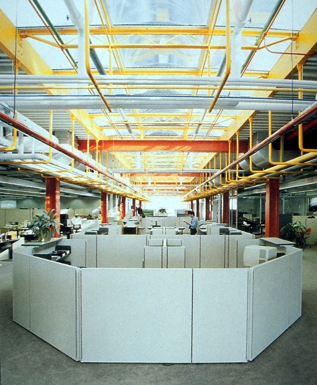 Figure 3.
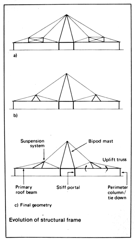 Figure 5.
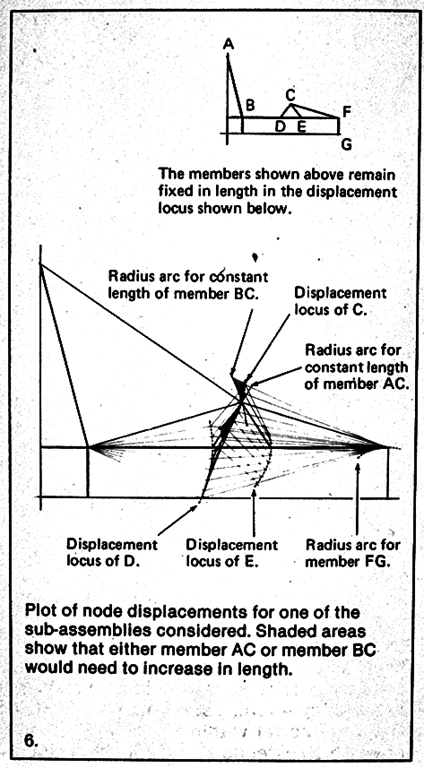 Figure 6.
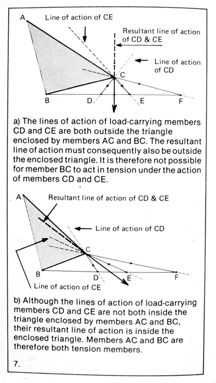 Figure 7.
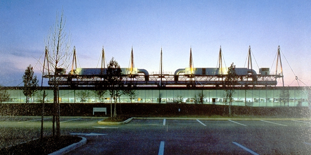 Figure 8.
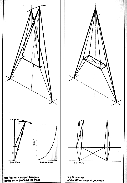 Figure 9.
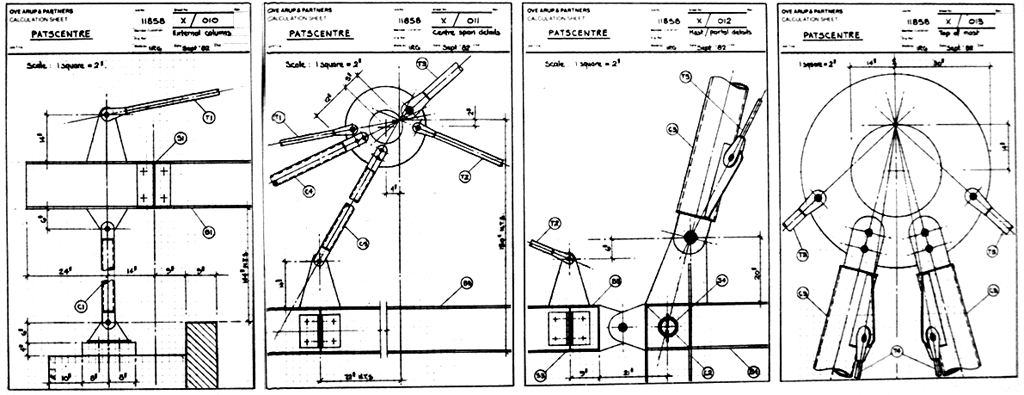 Figure 11.
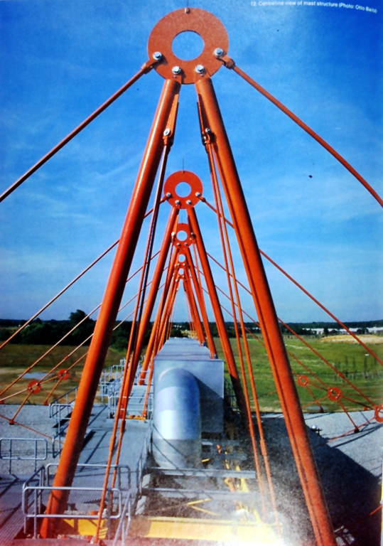 Figure 12.
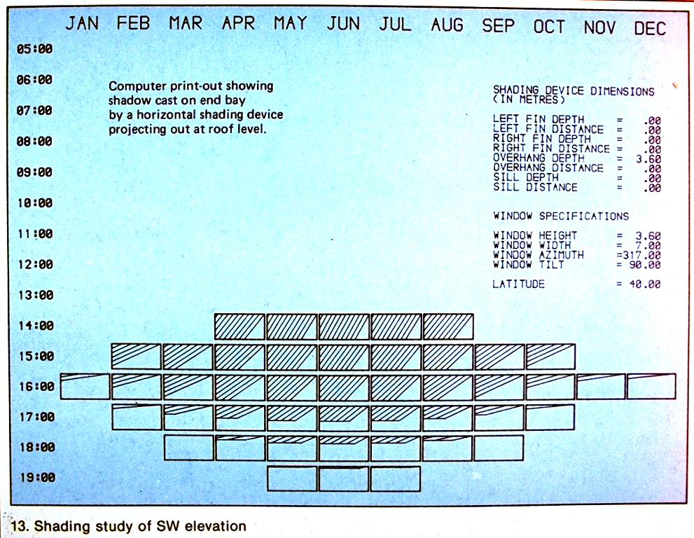 Figure 13.
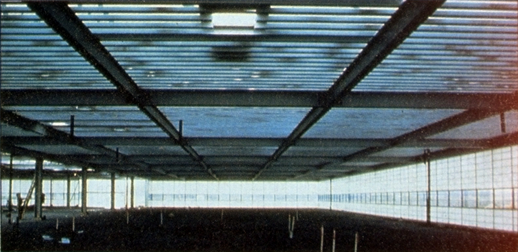 Figure 15.