Turbulent Flow: The Farnsworth House
Introduction
This example was modeled as closely as possible to the given boundary conditions of the Farnsworth house as a two dimensional case. Now that several cases involving rectangular cavities heated from below have been analyzed, it seems appropriate that this should be the next step.
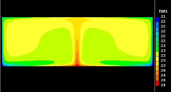
Physically, the cavity is 2.9m high and 8.7m wide, revealing an aspect ratio slightly less than three. The top wall is 19.4 C, the bottom wall is 33.3 C, and the two side walls are 9.4 C. The inside air is maintained at an average temperature of approximately 22 C and is considered an ideal gas with appropriate reference properties assigned. In addition, a thirty by ninety (2700 cell) mesh is used with no stretching factor.
Graphical Representations of Selected Results
-
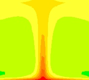
 Temperature Field (K)
-
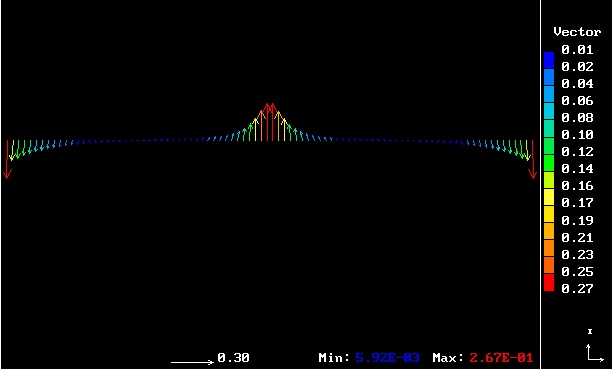
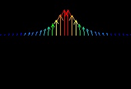 Velocity Profile (m/sec)
-
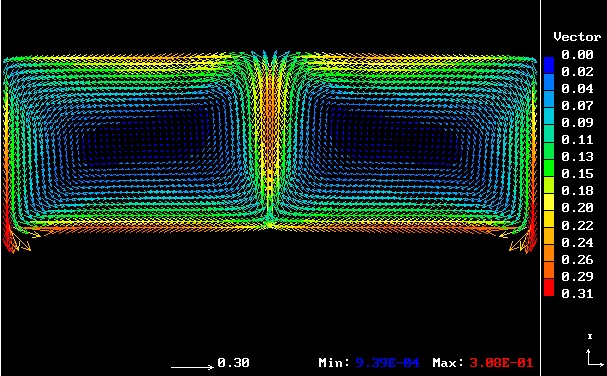
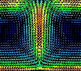 Velocity Field (m/sec)
-
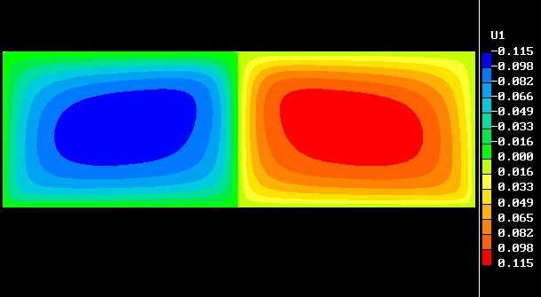
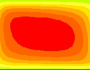 Streamline Contour (m^2/sec)
 Temperature Field (K)
 Velocity Profile (m/sec)
 Velocity Field (m/sec)
 Streamline Contour (m^2/sec)
Analysis:
Despite the seemingly coarse mesh for such a case, Y+ values are within the designated range for proper convergence's. In fact, finer meshes produce mass and energy net sources that do not balance, as well as Y+ values that are too small.
Once more, as in case1 and case2, a pair of dominant vortices are formed within the Farnsworth house model. Because the two side walls are assigned the lowest temperatures, cold air drops along the vertical edges of the periphery. Correspondingly, hot air rises in the central region as cooler air from the top wall descends. Two resulting circular regions of air flow develop with a maximum velocity of 31 cm/sec.