We also describe a hypermedia database, currently under construction, depicting major, twentieth century American buildings. The interactive, multidisciplinary elements of the database-- including structural and thermal analyses, free body diagrams (which show how forces are resisted by portions of a structure under various loading conditions), facsimiles of construction documents, and critical essays--are bound together and made available over the World-Wide Web. Finally, we discuss the relationships among all these projects, and their potential applications to teaching architecture students and to construction, assembly, and repair of complex structures.
- Introduction
Architectural applications are well represented in computer graphics. Most commonly, rendered animations of proposed or existing spaces are designed and presented on personal computers and workstations using a variety of applications (e.g., (Autodesk, 1994;Virtus94)). Through the use of texture maps and sophisticated lighting models, increasingly accurate representations of the appearance of complex environments are being constructed (Baum, 1991). These technologies have allowed the creation of intriguing, remarkably lifelike animations and renderings of unbuilt projects by architectural masters, such as Louis Kahn's Churva Synagogue (Larson, 1993). Through the use of head-mounted displays and 3D interaction devices, the user can walk through virtual architectural environments (Brooks, 1986). For example, one recent project allows distant networked users to jointly explore a re-creation of the Abbaye de Cluny, which in real life is now a ruin (Joscelyne, 1994).
Common to all these ventures into virtual architectural space is the intent to mimic perceived ``real'' space as closely as possible. Vast amounts of computational power have been expended, for example, to properly imitate natural and artificial lighting effects in these virtual spaces. This obsession with realism has had many benefits. For example, it has made it much easier for nonprofessionals, especially clients, to understand the nature of proposed spaces than was ever possible through the traditional methods of presentation, including plans, sections, perspectives, and small scale models. On the other hand, the quest for visual realism has left unexplored the potential of the computer to shed light where reality cannot. We are interested in using virtual worlds to help understand architecture in ways that are impossible to achieve by simply viewing the perceptual reality of completed spaces. Specifically, we are building systems that help us illustrate, understand, and modify architectural anatomy--the technical-utilitarian structural, environmental, and enclosure systems that support and service perceived space. This paper provides an overview of the early stages of three related research projects that focus primarily on structural systems, and their relationships to perceived architectural space.
- Augmented Reality for Architectural Anatomy
In our first project, we have applied our existing augmented reality testbed (Feiner, MacIntyre, & Seligmann, 1993) to expose a building's architectural anatomy, allowing the user to see its otherwise hidden structural systems. In the spirit of the first see-through head-mounted display developed by Sutherland (Sutherland, 1968), we and other researchers (e.g., (Robinett, 1992;Caudell- Mizell92)) use the term augmented reality to refer to systems that enrich the real world with a complementary virtual world. Our testbed supports a see-through head-mounted display that overlays a virtual world over the real world, using a mirror beam splitter to merge synthesized graphics with the user's view of the world. Figure 1 shows our current head-mounted display, which uses a Reflection Technology Private Eye display and Logitech ultrasonic tracker. Its graphics are rendered at 720*280 resolution and, in the application described here, include 3D vectors without hidden-line removal.
We provide support for 2D applications through a full memory-mapped X11 Window System (Scheifler & Gettys, 1986) server. The X11 bitmap is treated as if it were projected onto a portion of the surface of a virtual sphere surrounding the user and is composited with the bitmap containing the 3D graphics for presentation on the head-mounted display (Feiner et al., 1993). Our augmented reality testbed allows an X11 window to be positioned so that a selected point on the window is fixed at an arbitrary position within the 3D world. We refer to such windows as world-fixed windows. A world-fixed window's 3D location is projected onto the virtual sphere, yielding a 2D location in the X11 bitmap. As the position and orientation of the user's head change, each world-fixed window is automatically moved within the X11 bitmap to maintain a constant position within the 3D world. We take into account the roll, pitch, and yaw of the user's head in computing the mapping of a window's selected point from 3D to 2D. For reasons of efficiency and image quality, only conventional X11 window motion is supported. Thus, a window's image is always a fixed-size upright rectangle: it does not roll with the user's head and remains parallel to the plane of the display.
Our prototype application overlays a graphical representation of portions of a building's structural systems over a user's view of the room in which they are standing. We have built a partial model of Columbia's Schapiro Center for Physical Science and Engineering Research, which contains portions of the joists, beams, and columns that are in and near the lab in which our work is being performed. The model is based on the construction drawings provided by the building's architects. Figure 2 is a view of a corner of our lab photographed through our head-mounted display. The overlaid virtual world includes the outlines of parts of two support columns and the space between the structural concrete floor and the raised lab floor above it. The rightmost, larger column is inside the protrusion in the corner. (The representation of this column does not line up exactly with the visible walls because the physical column is not flush with the walls.) The other, smaller column is actually located in a nearby room. Figure 3 shows a view of the larger column with a different smaller, distant column, this time taken with the user looking up toward the ceiling of the room, such that part of the column extending into the next floor is visible.
Our prototype allows the user to select a column in order to see it in more detail. We accomplish this by interpreting mouse pointer events on the X11 root window as affecting the 3D objects that project to the cursor position on the head-mounted display. In Figure 4, the user has selected the leftmost column, causing the outlines of the support structures to dim. (Our current display hardware is one-bit deep, so dimming is accomplished through the use of different line styles; in this case, dotted lines.) After a short delay, the reinforcing steel bar (re-bar) internal to the column is revealed, as shown in Figure 5. In addition, a structural analysis of the column is presented to the user. This information is provided by a world-fixed X11 window that allows the user to scroll through a textual analysis of the column produced by Dast, a commercially available structural analysis and design program (Das, 1993).
The structural-analysis window appears near the column being analyzed, with its upper left corner attached to the center of the column. This is the first step toward our eventual goal of being able to manipulate the geometry of the column and see the resulting changes in column strength reflected in the displayed output of the analysis program. As described in Section 4, we are also interested in augmenting the world with additional architectural information.
Building on our work on knowledge-based augmented reality for maintenance and repair (Feiner, MacIntyre, & Seligmann, 1993), we are developing a knowledge-based system that will dynamically control which parts of the structural system are displayed to satisfy the user's goals in exploring the environment. We envision that a mature version of our system could find application in both maintenance and construction. For example, during construction, it could be used by an inspector to verify that the specified re-bar is placed correctly before concrete is poured; similarly, if the concrete mix as measured in the field was not as specified in the construction documents, the structural analysis program could report instantly if this caused a structural problem.
- Unhiding Lines: Superposed Structure in 3-D Architectural
Animations
In this project, we use conventional modeling and rendering software (SoftImage, 1994) to create an animated version of the room described above for display on a color CRT. As in the augmented reality project, for which this project also served as a preliminary prototype, the visual representation of the room is overlaid with a graphical representation of its structure. To make the structural components more legible, their extent is limited by foreground and background ``section cuts.'' Figure 6 shows an image created by this project, focusing on the column in the corner of the room diagonally across from that shown in Figure 5. That the structure displayed is concrete is suggested by the visible re-bar and its extension beyond appropriate section cuts. Here we use hand culling and sectioning of concrete and re-bar to limit the displayed extents of these
All structural components and finish materials (e.g., painted gypsum board and hung ceiling) are modeled as 3D objects, which allows us to vary their opacity independently. By simply manipulating the opacity of various materials, the user can opt to view any combination of re-bar, concrete, and finish surfaces. In this animated prototype, we have used this technique to determine what components to include as well as how much detail of a particular component to show as a function of the user's proximity to it. For example, we have found that showing all the re-bar inside a column is visually confusing unless the user is nearby.
Our experience developing and using this system is helping to point the way towards the creation of an effective set of architectural visualization rules for use in our augmented reality system. This project also complements our augmented reality work in that it does not require that the user either be physically in a space or have access to a head-mounted display to study its structure and to discern its relationship to perceived architectural boundaries. We believe that workstation displays of this sort could be used by architectural students, as well as by practitioners responsible for the coordination of building finishes and structure.
- An Architectural Anatomy Database
In a third project, we are developing the Architectural Anatomy Database, an interactive multimedia database of major twentieth- century American architectural works. Unlike the photorealistic walkthrough projects noted in the introduction, the Architectural Anatomy Database includes a variety of interdisciplinary information--including structural and thermal analyses, 3D details and free body diagrams, facsimiles of construction documents, and critical essays--that illustrates the nature of a building's structure, mechanical systems, and building envelope. This presentation allows users to analyze a variety of technical information interactively and in detail, in a way that highlights the mutual interdependence of technical systems, and their effect on the perceived architectural space and form.
The database is a set of hypermedia documents written for World-Wide Web (WWW) browsers, such as Mosaic (Mosaic, 1994), which can spawn local software including 3D modeling tools, structural analysis software, and spreadsheets. Each document corresponds to the analysis of a single building. A text and graphic-based building description and critique serves as the initial interface, and contains hypertext links to animated fly-throughs of the building, structural and thermal analyses, essays and facsimiles of construction documents. This interdisciplinary database illustrates the types of information we may like to make available in the future through augmented reality. We are currently working with students, practitioners, and scholars to see which information is most useful to each group.
Our first document (Webster, 1994) is an analysis of the PATCenter by Richard Rogers and Partners. Details and photographs of the PATCenter are displayed graphically as hypertext links from the text-based critical analysis, and include a cutaway axonometric view of the building, typical structural, enclosure and HVAC details, and building free-body diagrams for gravity and wind loads (Figures 7 and 8). The database's presentation of Ludwig Mies van der Rohe's Farnsworth House makes more extensive use of the WWW browser as an integrated interface--spawning various applications to illustrate particular aspects of a project. In addition to critical essays and construction documents, the Farnsworth module includes an introductory animated fly-through, a thermal analysis of the building enclosure system, and 3D models analogous to the axonometric drawings presented for the PATCenter. Also included are a Dast-based structural analysis, and an animation showing the relationship between the building's visually perceived space and the structural components supporting it, how loads are transferred among these components, and how these loads cause them to deflect (Figures 9 and 10).
We expect that the Architectural Anatomy Database will be used as a resource by students and architectural scholars for both architectural and engineering education, and for technical and historical research into building construction techniques. The Farnsworth module will be used in the classroom to teach both structural engineering and heat-transfer basics to incoming engineering students next year. The Architectural Anatomy Database is ultimately intended to include information stored on servers at other institutions. This capability is particularly important for access to architectural archives, which because of their size, are often difficult to reproduce or loan (Sim, 1991). Incorporated into the Architectural Anatomy Database, information from such disparate sources as the R. Buckminister Fuller Archives in Texas, the Frank Lloyd Wright Foundation in Arizona, and the Louis Kahn Papers at the University of Pennsylvania can be perused as if it were at one location, by any number of simultaneous users.
While the Architectural Anatomy Database is currently designed to be explored on a conventional workstation display, we are interested in how the material that it contains could be tied to the real or virtual space presented in the previously described projects. In particular, we would like to make it possible for a student to inspect the material that documents a building's structure while exploring that building in our augmented reality. For example, attached to a portion of the building facade could be a video of its construction, the details of its thermal and waterproofing systems, and a description of the influence of its materials on the expression of the building exterior. We expect to accomplish this through the facilities that we currently use to display the results of the structural analysis program. Our augmented reality testbed already allows us to position arbitrary X11 windows so that they are located at a selected location relative to the user's head, relative to a wearable wrap-around virtual ``information surround,'' or relative to the 3D physical world (Feiner et al., 1993). It also allows us to make hypertextual links between these windows and objects in the physical world. This will provide the framework through which the contents of our WWW database can be tied to parts of a virtual or physical building that it documents. We intend to work with architecture students and scholars to establish the types of information that would be useful to present in this fashion.
- Conclusions
Traditional forms of architectural representation are limited in the singularity of their point of view. The photorealistic representations described in the introduction to this paper have greatly improved the ability to understand a building spatially-- whether it be a proposed, existing, or reconstructed work. We expect that some of the techniques presented here will have a similarly beneficial effect on a designer's comprehension of technical- utilitarian systems, and their construction, assembly and relationship to a finished product.
In teaching architectural technology, for example, we anticipate a number of specific benefits. Traditional forms of representation (photos and drawings) severely inhibit learning about how architectural structures are made, how they work, and how they influence an inhabitant's perception of architectural space. Drawings take a long time to prepare interactively (on a blackboard), and their single point of view is limiting. Animated tours of architectural spaces, which show simultaneously finished surfaces and structural underpinning from a potentially infinite number of perspectives, could improve both the rate and depth of comprehension of architectural structures.
Developing a sense of ``tectonic reality'' (what our many-layered building systems are materially comprised of and how they are assembled) is also hampered by the limits of hands-on building projects and field trips. The usefulness of field trips is limited by how much one can see in a particular time and what is going on at the time of the visit, as well as by the (small) number of people who can attend. Descendants of the augmented reality system described above may go a long way towards making site visits more educationally effective by using ``x-ray'' vision to see work previously completed, as well as that happening at the time of the visit, or even to view the future state of the finished project.
We are especially hopeful that future commercial use of the techniques described here will help increase both the accuracy and efficiency of building construction. Currently, those charged with making a building a physical reality must rely on relatively abstract, two-dimensional representations of the projected building, and spend much of their time mentally translating from two to three dimensions. Too often, either something is omitted in the translation or it is determined that the building's designer is proposing something that cannot be built in the real, 3D world. This is a problem that can have catastrophic consequences. For example, the collapse of the Kansas City Hyatt's suspended walkways in 1981, and the failure of the Hartford Civic Center Arena's roof in 1978 are directly attributable to lack of understanding of assembly and buckling in three dimensions, respectively (Levy & Salvadori, 1992). The use of augmented reality systems at actual construction sites by designers and constructors, should be able to help them anticipate and avoid potential catastrophes, while speeding the building process.
To fully exploit the rapidly increasing potential of virtual worlds and augmented reality, we believe it is essential to first ask what are we showing in them and why. Paradoxically, the answers have led us to the display of information not normally visible in reality in order to help us better make and understand our built reality.
ACKNOWLEDGMENTS
Portions of the Architectural Anatomy Database were put online by Robert Cartolano and Seth Strump of Columbia University's Academic Information Services and is maintained on a university server.
Research on the augmented reality project is supported in part by the Office of Naval Research under Contract N00014-94-1-0564, a gift from NYNEX Science & Technology, the New York State Center for Advanced Technology in Computers and Information Systems under Contract NYSSTF-CAT-92-053, the Columbia Center for Telecommunications Research under NSF Grant ECD-88-11111, NSF Grant CDA-92-23009, and equipment grants from the Hewlett-Packard Company and Ascension Technology.
Access to the SGI Onyx used for the architectural animation project is made possible by Columbia's Multimedia Initiative. The Farnsworth House animations were prepared by Chris Fox and Peter Oberdorfer of Columbia's Graduate School of Architecture. The authors would also like to thank Kenneth Kaplan for bringing them together.
REFERENCES
-
Autodesk, Inc. (1994). Literature on AutoCAD. Sausalito, CA:
-
Baum, D., Mann, S., Smith, K., and Winget, J. (July 1991). Making
Radiosity Usable: Automatic Preprocessing and Meshing Techniques
for the Generation of Accurate Radiosity Solutions. Computer
Graphics (Proc. SIGGRAPH '91), 25(4), 51-60.
-
Brooks, Jr., F. (October 23-24 1986). Walkthrough: A Dynamic
Graphics System for Simulating Virtual Buildings. Proc. 1986
Workshop on Interactive 3D Graphics. Chapel Hill, NC.
-
Das Consulting, Inc. (1993). Dast User's Manual. North Andover, MA:
Das Consulting, Inc.
-
Feiner, S., MacIntyre, B., Haupt, M., and Solomon, E. (November 3-51993).
Windows on the World: 2D Windows for 3D Augmented
Reality. Proc. UIST '93 (ACM Symp. on User Interface Software
and Technology). Atlanta, GA.
-
Feiner, S., MacIntyre, B., and Seligmann, D. (July 1993).
Knowledge-Based Augmented Reality. Communic. ACM, 36(7), 52-62.
-
Joscelyne, A. (January 1994). VR means Virtual Reconstruction:
Cluny Abbey has been Rebuilt. Wired, 2(1), 114-115.
-
Larson, K. (September 1993). A Virtual Landmark. Progressive
Architecture, 74(9), 80-87.
-
Levy, M. and Salvadori, M. (1992). Why Buildings Fall Down. NY, NY:
W.W. Norton.
-
NCSA Software Development Group. (1994). Documentation for Mosaic.
Urbana-Champaign, IL: National Center for Supercomputing
Applications.
-
Robinett, W. (Spring 1992). Synthetic Experience: A Taxonomy.
Presence, 1(2), 229-247.
-
Scheifler, R., and Gettys, J. (April 1986). The X Window System.
ACM Trans. on Graphics, 5(2), 79-109.
-
Sim, A. (May 1991). Collected Memories: A Last Ditch Attempt to
Record Britain's Disappearing Architectural Heritage. Blueprint,
(77), pp. 27-29.
-
SoftImage. (1994). Product Literature. SoftImage.
-
Sutherland, I. (1968). A Head-Mounted Three Dimensional Display.
Proc. FJCC 1968. Washington, DC, Thompson Books.
- Webster, A. (February 1994). Architectural Anatomy: PA Technology Center, Princeton, NJ. School of Architecture, Columbia University, NY, NY: Mosaic document http://www.cc.columbia.edu/ spr94courses/a4125y/patcenter/pat-center.html.
FIGURES
-
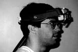 Figure 1:
The see-through head-mounted display used in our augmented reality system.
-
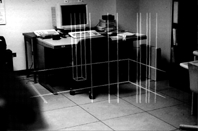 Figure 2:
A corner of our lab as seen through our head-mounted display. Overlaid graphics show the outlines of two columns and a representation of the space between the raised lab floor and the structural concrete floor below.
-
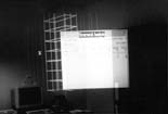 Figure 3:
Sections of the columns extending above our lab as seen through our head-mounted display. The user is looking upwards toward the ceiling.
-
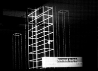 Figure 4:
Sections of the columns extending above our lab as seen through our head-mounted display. The column at the left has been selected by the user. The outlines of the support structures have been dimmed, by rendering them with dotted lines, prior to displa ying the structural details of the column.
-
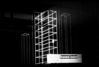 Figure 5:
The corner of our lab as seen through our head-mounted display. The column at the left has been selected by the user. Its internal re-bar is shown in the overlaid graphics, along with a window that displays a textual structural analysis obtained from an e xisting program.
-
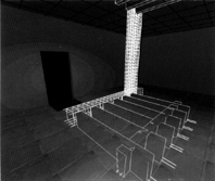 Figure 6:
View of our lab as depicted in the animated prototype for our augmented reality. The structural components shown are a portion of a column and beam, including their re-bar, and floor joists and a diaphragm parallel to the beam, showing re-bar only as it e xtends beyond their section cuts.
-
 Figure 7:
The PATCenter by Richard Rogers. Cutaway isometric view of building enclosure.
-
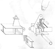 Figure 8:
The PATCenter by Richard Rogers. Cutaway isometric view of structural and roof details.
-
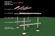 Figure 9:
The Farnsworth House by Ludwig Mies van der Rohe. Frame from an animation showing structural components and the loads and forces transferred among them.
-
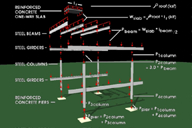 Figure 10:
The Farnsworth House by Ludwig Mies van der Rohe. Frame from an animation showing gravity-induced deflections of structural components.
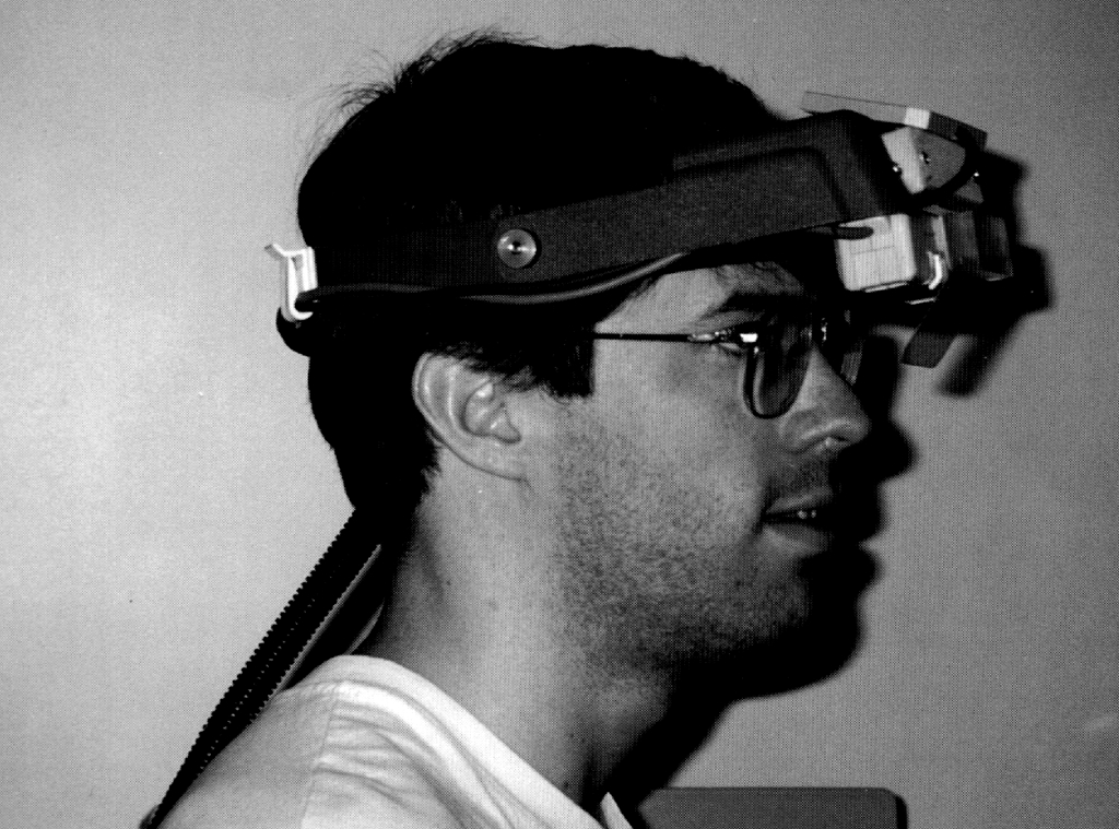 Figure 1:
 Figure 2:
 Figure 3:
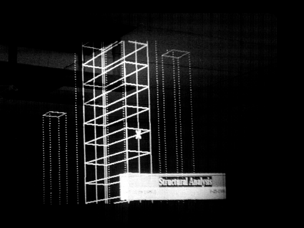 Figure 4:
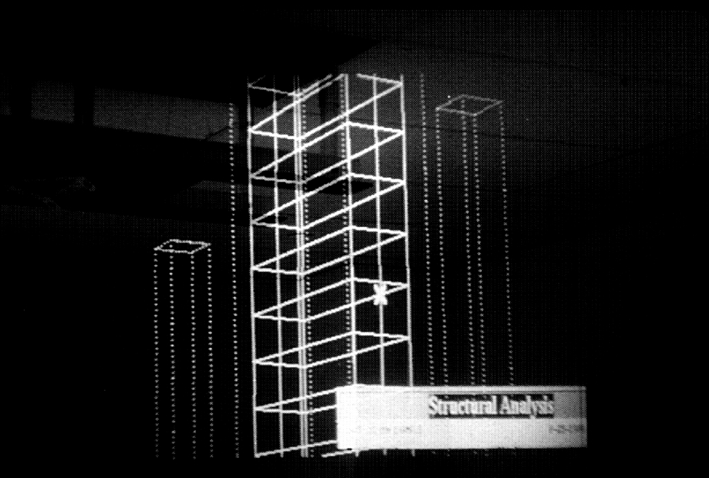 Figure 5:
 Figure 6:
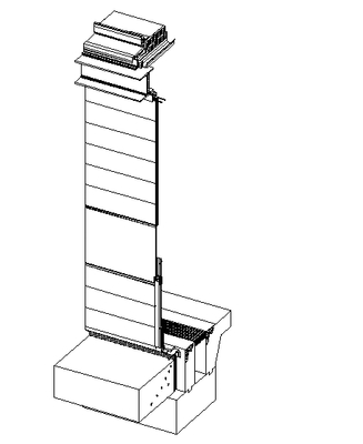 Figure 7:
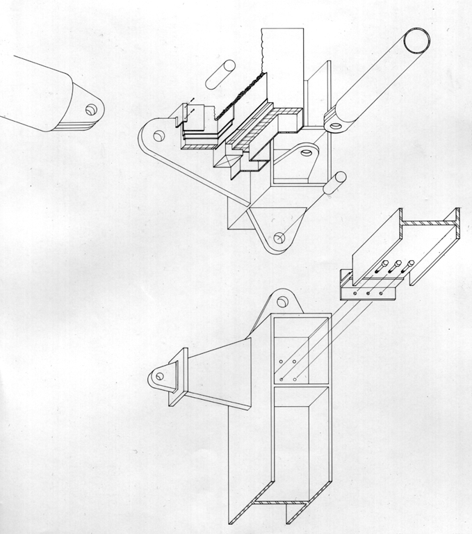 Figure 8:
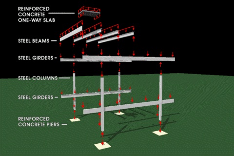 Figure 9:
 Figure 10: