
Precise leveling in New York City
(New York : J.J. Little & Ives Co., 1915)
|
||

 Click here and hold to drag menu around
|


|
|
|
|
| Page 25 |
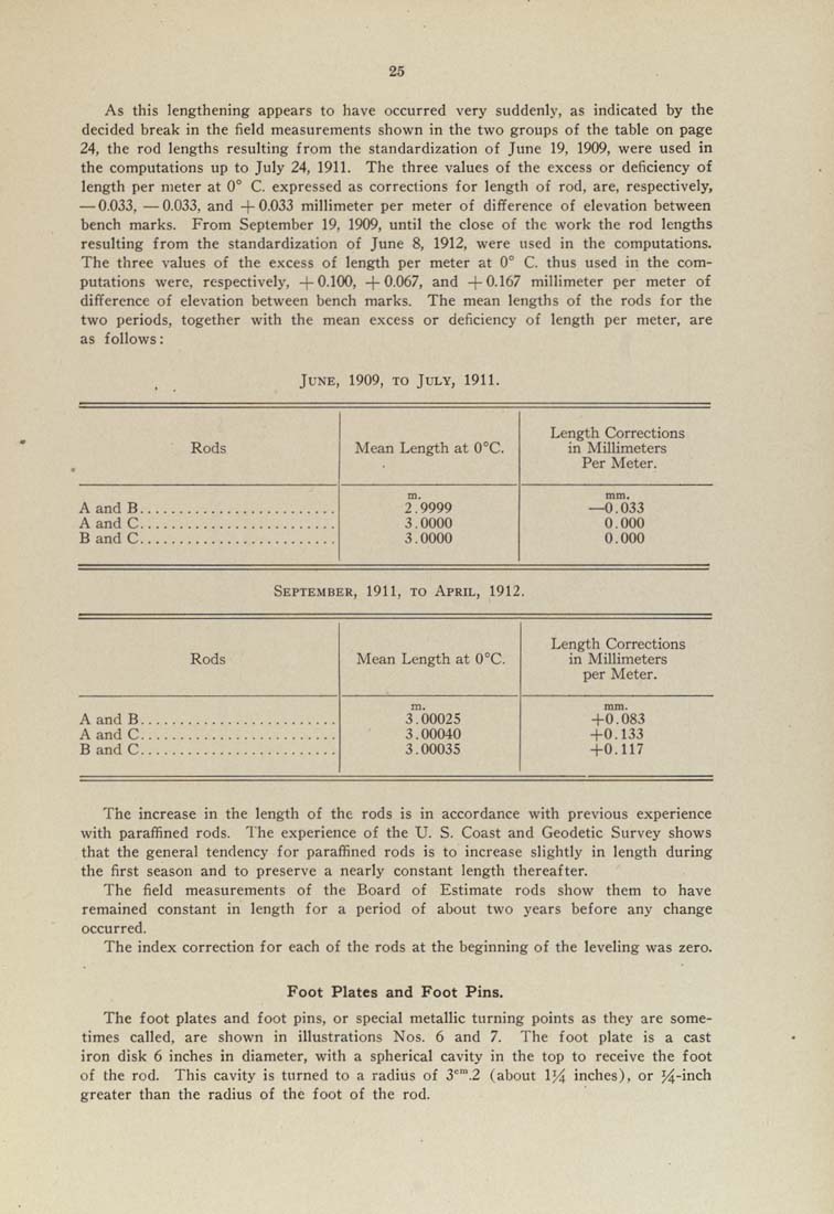
As this lengthening appears to have occurred very suddenly, as indicated by the decided break in the field measurements shown in the two groups of the table on page 24, the rod lengths resulting from the standardization of June 19. 1909, were used in the computations up to July 24, 1911, The three values of the excess or deficiency of length per meter at 0° C. expressed as corrections for length of rod, are, respectively, — 0,033, —0.033, and -|-0,033 millimeter per meter of difference of elevation between bench marks. From September 19, 1909, until the close of the work the rod lengths resulting from the standardization of June 8, 1912, were used in the computations. The three values of the excess of length per meter at 0° C. thus used in the com¬ putations were, respectively, -|-0,100, -(-0.067, and -|-0.167 millimeter per meter of difference of elevation between bench marks. The mean lengths of the rods for the two periods, together with the mean excess or deficiency of length per meter, are as follows: June, 1909, to July, 1911. Rods Mean Length at O^C. Length Corrections in Millimeters Per Meter. 2.9999 3,0000 3,0000 0.000 September, 1911, to April, 1912. Rods Mean Length at 0°C, Length Corrections in Millimeters per Meter. 3'"00025 3.00040 3,00035 -1-0,117 The increase in the length of the rods is in accordance with previous experience with paraffined rods. The experience of the U. S, Coast and Geodetic Survey shows that the general tendency for paraffined rods is to increase slightly in length during the first season and to preserve a nearly constant length thereafter. The field measurements of the Board of Estimate rods show them to have remained constant in length for a period of about two years before any change occurred. The index correction for each of the rods at the beginning of the leveling was zero. Foot Plates and Foot Pins. The foot plates and foot pins, or special metallic turning points as they are some¬ times called, are shown in illustrations Nos, 6 and 7. The foot plate is a cast iron disk 6 inches in diameter, with a spherical cavity in the top to receive the foot of the rod. This cavity is turned to a radius of 3'^'".2 (about 1J4 inches), or J4"i"*^ greater than the radius of the foot of the rod. |
| Page 25 |