How It Works The platform
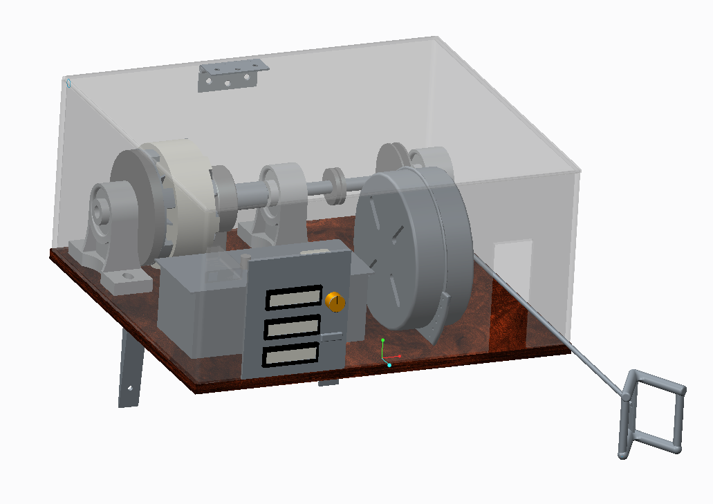
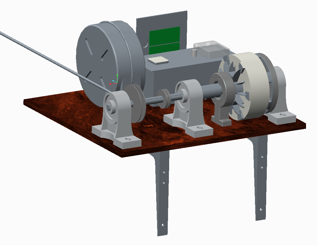
Maglift is an exercise device that provides the user with variable magnetic-based resistance controlled through a simple user interface. The system consists of three main mechanical components: a magnetic particle brake which provides resistance to the user, a dual spool mechanism to translate lateral into rotational motion, and a retraction mechanism. It is coupled together through a modular network of electronics.
Mechanics
The dual spools fit onto a shaft which is connected to the brake through a shaft coupler. One of the spools is connected to a nylon rope and handlebar. The other spool is connected to a retraction mechanism, which consists of a stainless steel cable attached to a spiral-wound torsion spring. As the user pulls on the handlebar, the nylon rope will begin to unwind from its spool. The rotation of the spool and connected shaft directly opposes the braking force of the magnetic brake. As the nylon rope unwinds, the retraction cable will wind around the retraction spool, causing tension in the torsion spring to increase. Once the user stops pulling, a tachometer system will indicate this stop in motion; in response, the brake will power down. The torsion spring will then force the retractor cable to unwind from the retraction spool, causing the shaft the rotate in the opposite direction until the system is back to its starting position.

Electronics
The 3D-printed user interface has a knob to turn up or down the resistance and three individual displays which show the weight the user is pulling, the rotations per minute of the particle brake shaft, and counts number of specified reps. This user interface connects to an Arduino Mega microcontroller and the modular electrical system to convert user inputs into the brake's smooth movements and resistance.
The NIIKA brake controller was made specifically for its accompanying magnetic particle brake. When the microcontroller receives the user's desired "weight" value, it reaches into its memory to find a digital pulse signal that generates the equivalent effect in the particle brake. Circuitry between the Arduino and the brake controller receives the Arduino's digital signal, converts and amplifies it into an analog signal for the controller.
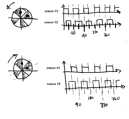 Quadrature in Encoding, Prof. David Vallancourt
During use, the tachometer subsystem is made of two hall effect sensors in quadrature, with four magnets attached to the shaft as triggers. Thus the tachometer is able to sense the clockwise or counterclockwise motion of the shaft, indicating user action or machine retraction, and accordingly power up or power down the brake. Throughout this action, the microcontroller is always sending information back to the user interface LCD screens for display.
Mechanical Specifications
As of now, the device is designed to only provide erg machine motions, but with proper linkages, the device is capable of delivering all range of motions. Moreover, the resistive source is capable of delivering resistance levels from the equivalent of 10lbs in the gym to well above 300lbs, while the supporting structures fulfill the safety margin of five by a substantial gap. The entire device has a weight of roughly 55 lbs and is very portable in comparison to traditional weight systems. Moreover, when programmed to do so, the machine can change the specified level of resistance within a set seamlessly.

Electrical Specifications
| Controller Voltage | 220V |
| Controller Current | 0.8A | Controller Power Consumption | 176W | Arduino Power Consumption | ‹0.4W (max) | also powers: | Hall Effect Sensors | Displays |
Behind the Scenes More research
Our team took the NIIKA POB-012 magnetic particle brake through extensive characterization and testing to understand the relationship between its RPM, its braking torque and its input voltage.
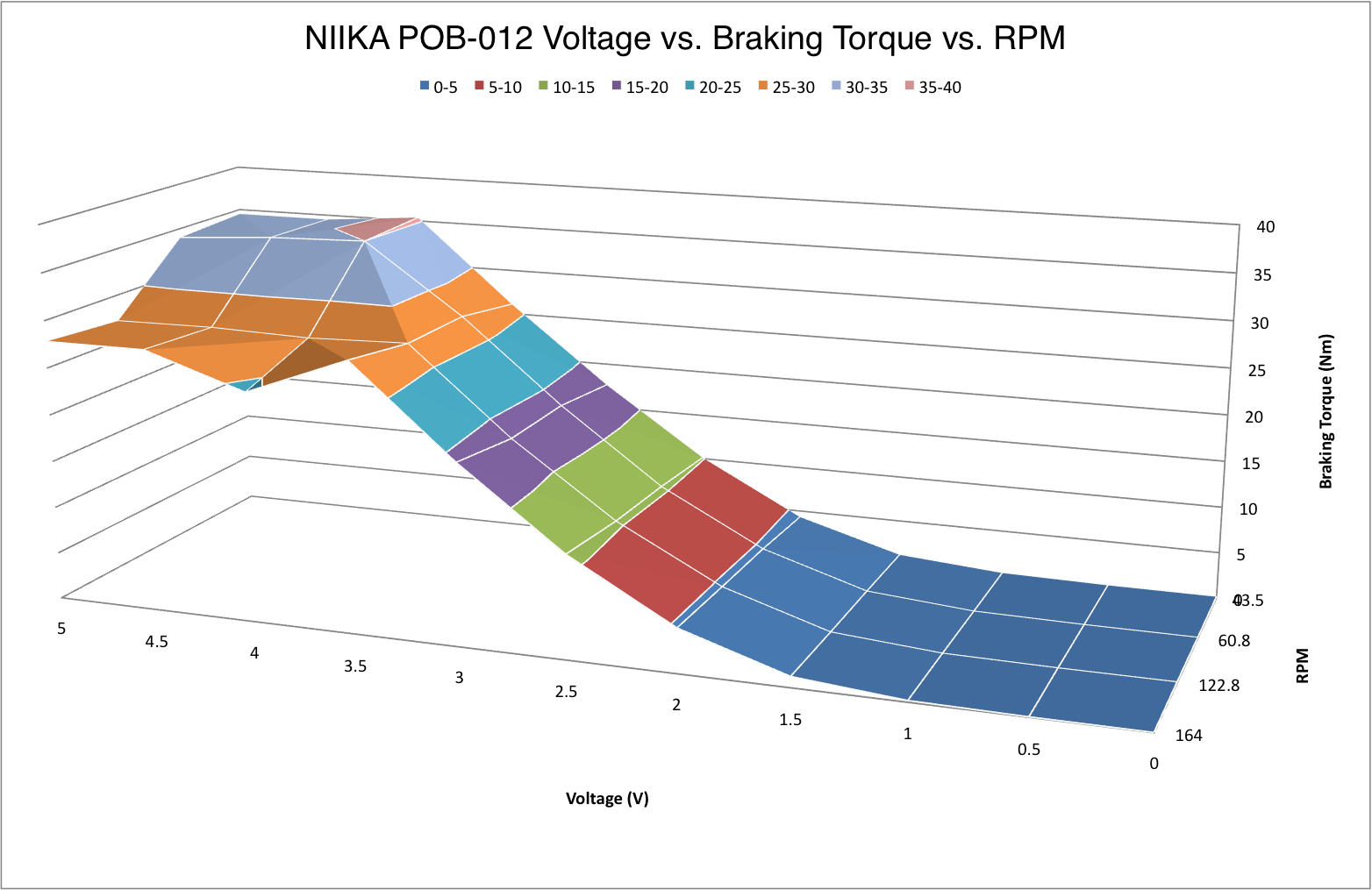
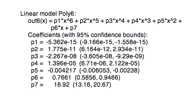
A model was created to calibrate the conversion of desired braking force input by the user to the appropriate digital pulse output generated by the Arduino -- these values are then stored in the Arduino.
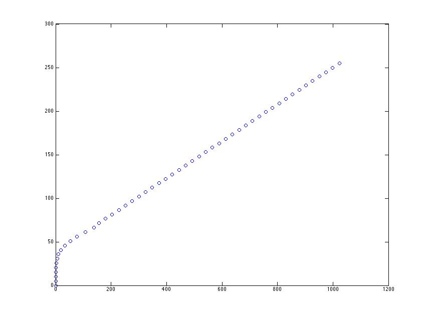 X-axis: input analog value selected by user
Y-axis : generated digital output