During initial examination, the size of the stomal opening was determined and recorded. The desired depth of the stomal obturator was determined by discussion with the patient’s otolaryngologist who was present. This depth was later tested to determine whether it was comfortable to the patient and did not interfere with airflow. A custom impression tray was constructed from base plate wax (TruWax, Dentsply/York Division, York, Pa.) and processed into clear acrylic resin (Hygenic clear laboratory resin, Hygenic Corp, Akron, Ohio) to the following specifications: (a) external flange and handle: 38 × 25 mm oval with solid external handle; (b) Perforated stem 31 × 7 × 2 mm. Length includes terminal bulb. Similar angulation as tracheostomy tube; (c) terminal bulb diameter of the external stomal opening.
The patient returned to the Department of Otolaryngology/Head and Neck Surgery and, with the otolaryngologist present, the impression tray was tried in place to determine resistance to removal and relative comfort to the patient. The patient was able to breathe freely through the mouth and nose with comfort. The internal surface of the external flange, the stem, and the bulb were painted with Express polyvinyl siloxane (PVS) adhesive (3M, St Paul, Minn.) and then allowed to dry.
Equal amounts of Express PVS putty catalyst and base paste were mixed together and adapted to the terminal bulb and stem of the custom impression tray, ensuring that the perforations within the stem were well engaged. The impression tray was firmly seated to place in the stoma, then gently removed and worked back into place a second time to ensure passive fit. The patient then was instructed to perform functional movements of the head and neck
(Fig. 2).
Fig. 2. Impression of tracheostomal defect with patient performing functional movements of head and neck.
|
|
|
Click on Image to view full size
|
Once set, the impression was removed and light-body PVS was syringed to the undersurface of the external flange and reseated. The patient repeated functional movements of the head and neck to capture an accurate impression of the external tissue during movements. The resultant prosthesis is illustrated in
Figure 1 adjacent to a pre-formed tracheostomy tube. The curvature of the prosthesis is similar to that of the pre-formed tube.
A tentative color match was performed using medical adhesive A (Dow Corning, Midland, Mich.) and silicone paste color concentrates dispersed in liquid silicone (Factor 11, Lakeside, Ariz.). This was used later as a guide for coloration of the silicone prosthesis. The impression was embedded into a vacuum mixed dental stone (Lab Stone-Buff, Modern Materials, Port Washington, N.Y.) in a disposable paper cup. The resultant mold was then scored and split and the impression was recovered and the mold reassembled.
Two flanges 4 mm in length each were added to the terminal bulb of the recovered impression. At this time, a second mold was poured. This was also scored and the impression recovered. Tops of both molds were smoothed with sandpaper and baseplate wax was added to their tops to form external flanges 38 × 25 × 2 mm. The top of each mold was notched, and a cap was poured to fit each. The wax was boiled out and the molds allowed to cool. COE-Sep tinfoil substitute (GC America, Chicago, Ill.) was painted to all surfaces of each mold that would come into contact with the prosthesis
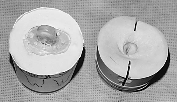
(Fig. 3) so that it could be easily removed from the mold when completed.
Fig. 3. Functional impression poured and duplicated. Stone cast on right shows how cast was scored and fractured to remove impression intact and reassembled for creation of tracheostomal obturator.
|
|
|
Click on Image to view full size
|
Medical adhesive A was mixed with pigments to attain a color match with the patient’s skin tone in proportions that were determined previously. This mix was applied to the molds that were assembled and allowed to cure. The resultant prostheses were removed from their respective molds and trimmed.
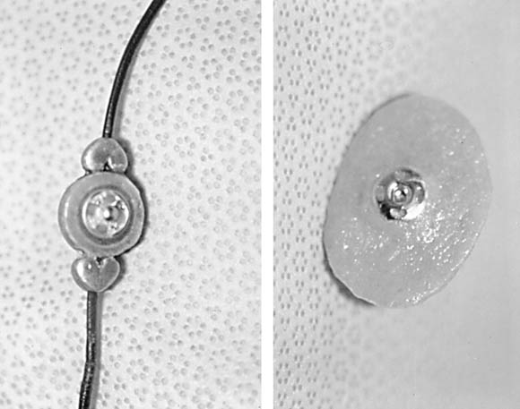
A beaded necklace was assembled with parts from a local crafts store. The rear of the central bead was flattened, and the patrix portion of a clothing snap assembly was secured into place using autopolymerizing clear orthodontic resin
(Fig. 4).
Fig. 4. Tracheostomal obturator assembly. Left, rear of beaded necklace with patrix portion of clothing snap luted to it. Right is tracheostomal obturator with matrix portion of clothing snap assembly used for retention.
|
|
|
Click on Image to view full size
|
The corresponding matrix portion of the snap assembly was secured with ligature wire to a small square of metal meshwork. A recess was cut into the center of the external surface of the prosthesis with a scalpel blade approximating the size of the metal mesh containing the matrix portion of the snap.
A second batch of Medical adhesive A and pigment was mixed in the same relative amounts as the first batch. This was used as a luting and a camouflaging agent, securing the metal mesh to the center of the prosthesis and disguising it to the eye. At the delivery appointment, the necklace was fitted to the patient with the prosthesis in place
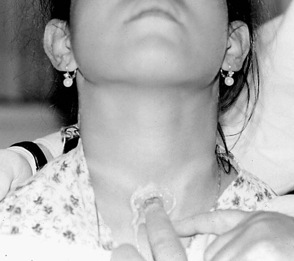
(Fig. 5).
Fig. 5. Ten-year-old girl with CCHS with tracheostomal obturator assembly in place. Prosthesis is esthetically pleasing to patient and held in place through bulb on terminal end of obturator with beaded necklace.
|

|
|
Click on Image to view full size
|
It was determined that the retentive flanges were not necessary for this patient. Not only were the flanges a source of irritation to the patient, but also because this prosthesis was resistant to removal with only the bulb in place. The necklace provided additional retention. On coughing, the prosthesis was secure, and there was virtually no air escape during speech.
This clinical report describes the treatment of a patient with Congenital Central Hypoventilation Syndrome using a simple impression procedure and prosthesis fabrication. Treatment required only the basic information provided by the otolaryngologist, measurements were taken at the initial appointment, and basic skills were used in fabrication of intraoral and extraoral prosthetic devices. It is recommended that the clinical phase of this procedure be performed in the presence of an otolaryngologist. Patients who live with this syndrome have undergone many trials physically, emotionally, psychologically, and socially. The presence of this type of prosthesis has many advantages such as allowance of speech without obvious air leakage, and being relatively inconspicuous. Compared with the alternative, this type of prosthesis allows these patients to feel less conspicuous.
1. Mellins RB, Balfour HH, Turing GM, Winters RW. Failure of automatic control of ventilation (Ondine’s Curse). Medicine 1970;49:487-504.
2. Oren J, Kelly D, Shannon DC. Long-term follow-up of children with congenital central hypoventilation syndrome. Pediatrics 1987;80:375-80.
3. Ma T, Ross JC. A technique for fabrication of a custom tracheostomy prosthesis. J Prosthet Dent 1989;62:668-71.
4. Jacob RF, Bowman JB. A custom tracheostomal valve retainer for the laryngectomy patient. J Prosthet Dent 1987;57:479-82.
5. Grisius RJ, Moore DJ, Simpkins WT Jr. Prosthetic treatment of the laryngectomized patient. J Prosthet Dent 1974;32:300-6.
- aAssociate Professor and Director, Division of Prosthodontics; Program Director, Maxillofacial Prosthetics Residency.
bAssistant Professor of Clinical Dentistry.
cAssociate in Clinical Dentistry.
dAssociate Professor of Clinical Medicine, Otolaryngology/Head and Neck Surgery, and Director of Pediatric Otolaryngology.
eResident in Maxillofacial Prosthetics.
- J Prosthet Dent 1999;82:387-90.
- Reprint requests to: DR ROBERT F. WRIGHT, 630 WEST 168 ST, PH 7-EAST ROOM 115, NEW YORK, NY 10032, FAX: (212)305-5679, E-MAIL: [email protected]
Copyright © 1999 by The Editorial Council of The Journal of Prosthetic Dentistry.
- 0022-3913/99/$8.00 + 0. 10/1/101565

)
)
)
)
)