Photo Gallery...
The Columbia University Computer Center in 1965
| Photographer: | Unknown |
| Source: | Columbia University Archives. For permission to use the photos below, send email to [email protected] referencing this page and Box 129 of the Historical Photograph Collection. |
| News: | The IBM 7090, which was an earlier version of the 7094 shown just below, is featured in the 2017 film Hidden Figures, about the unsung role played by Black women in the early NASA space program. |

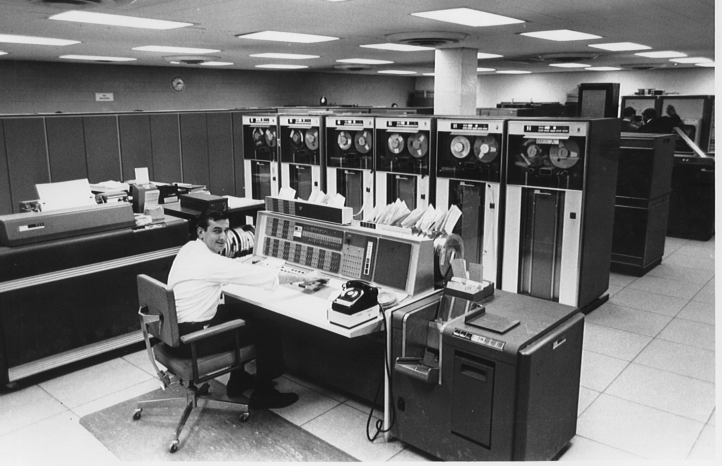
Mike Barrett, the first Computer Center Operations Manager, at the console of the IBM 7094, the senior partner in the 7094/7040 Directly Coupled System (DCS or DCMUP) arrangement. To the right is the operator's card reader. Tape drives in center. The cabinets against the left wall are full of core memory. Disks and various control units are behind the tape drives.
On the left is what looks like an IBM 407 Accounting
Machine, but isn't*. Nevertheless, Peter G. Capek of the present IBM Thomas
J. Watson Research Center in Yorktown Heights, NY (who was a student at
Columbia from 1965 to '69 and also spent some time at Watson Lab on 115th Street before that, under the
auspices of the high school Science Honors Program, where he did some work
on the 650 and the 1620),
reports that the 407 "was the 7094's 'console printer'.. lists job start and
stop times, errors, accounting info, etc. I suspect in the DCS
configuration (with 7044) this was vestigial, but probably still needed to
run diagnostics, stand-alone, etc. I think the 407 used for this purpose
didn't even have the card reader (and as a result, is about a foot
narrower), but I can't tell from your photos, and I don't remember for sure.
The 407 also had the closest thing (when running non-DCS, anyway) to a
time-of-day clock. It was a mechanical clock built into the 407 and counted
100ths of a minute. The 709x would interrogate the clock at the start and
end of each job. Interrogating it was kind of interesting, because it
involved printing the clock value on the printer, terminating the cycle
before it actually made a mark on the paper, and then using the "echo
checking" feature of the printer to fetch the actual value. Echo checking
was a way for the program to make sure that the mechanical printer had
actually printed the correct digit on the paper. The side effect of this is
that if the program running interrogated the clock (say, with a call from
Fortran, or if the operating system did it between steps of a job), the
printer made a funny noise -- like printing, but not quite."
__________________________
| * | In March 2006, Jordan L. Stedman of Prodata Systems Inc wrote:
I took note of the following text in the second paragraph: "On the left is an IBM 407 Accounting Machine." Actually, the device in question is the IBM 716 printer, which was very similar to the infamous 407. Comparing this photo with the one of a bonafide 407, the only difference I could see was the placement of the nameplate on the printing unit. In the higher-resolution version of the same photo, I was able to zoom in on the nameplate and it's definitely a seven-one-something!
The 716 differed, however, in that it did not have an integral card reader and it had a much smaller wiring ("programming") panel. It also had a lot fewer relays, and the real 407 may have included some thyratron circuits not found in the 716. What it shared was the mechanical Print Analyzer-a piece of mechanical genius worthy of a Rube Goldberg award, that spun the type wheels and controlled their impact on the ribbon and paper so as to reproduce the desired glyphs. (This refers to the use of columns 73-80 of the 80-column punched card for sequence numbers.)
Of course, in the DCS configuration, the 716 and 711 were generally only used to run diagnostic programs specific to the 7094: all other I/O was usually directed through the 7040. |
John Van Gardner adds in May 2006:
I am glad to see you have corrected the misidentification of the the 716 as a 407 after an excellent message from Jordan L. Stedman.There are two other visual external differences between the two machines. The 716 does not have a card joggler plate on top of the carriage cover. The 716 being shorter than a 407 used a single piece lower front cover. The 407's lower front cover was split in the middle. You can see this in the 407 link on your page. You can also see the 4 spring loaded flap covers over the cover latches. The 716 cover only had two of these and it was a very heavy cover.
The analyzer unit was an ingenious device. The drive mechanism Jordan talks of was called the variable speed drive. Its purpose was to spin the type wheels to the correct position as they were being pivoted into contact with the paper, but to bring their rotation to a stop at contact time. This prevented any smudge printing. Another feature was the fluted reamer shaft that drove the prints wheels into the paper spiraled. This prevented all the type wheels from contacting the paper at one time. This greatly reduced the load and noise when printing a line of the the same character.
There were no Thyratrons in a 407. I think Jordan is thinking of the 717 which was used with 757 Control Unit and a 727 Tape Unit as an off line Tape to Printer system. It was mechanically identical to a 716 but It had two electronic gates with Thyratrons to drive the core storage buffer ring.
We had one of the OEM time of day clocks on our 716 at Lockheed Georgia Division. It was later replace with one that was more precise that acted like a tape drive. You just did a read select to that tape drive address and you got a data record indicating the date and time.
One little piece of tourist information. When IBM was developing the 701 system they needed a reader, punch and printer. They decided to adapt the best of the current products. The 407 would make a good printer but the card reader in the 407 was only 150 cards per minute. It had been designed to give the 407 a feature called MLR (Multiple Line Read). Each card came to a complete stop over a bed of contacts for each possible hole in the card. The read brushes were lowered onto the card and could sit there and read for as many cycles as desired. This type of arrangement could not be speeded up by much so they reverted back to the reader feed used in the 402. It was a continuous feed from the time the card left the hopper until it was in the stacker. They increased the speed to 250 cards per minute and put this feed in a separate frame and called it the 711. They also changed the one tooth ratchet clutch to a four tooth ratchet to reduce the time for the clutch to engage.
Regards,
John Van Gardner
IBM Retired Field Engineering Specialist
http://www.ed-thelen.org/comp-hist/storiesVanGardner.html
CLICK ON IMAGE to enlarge.
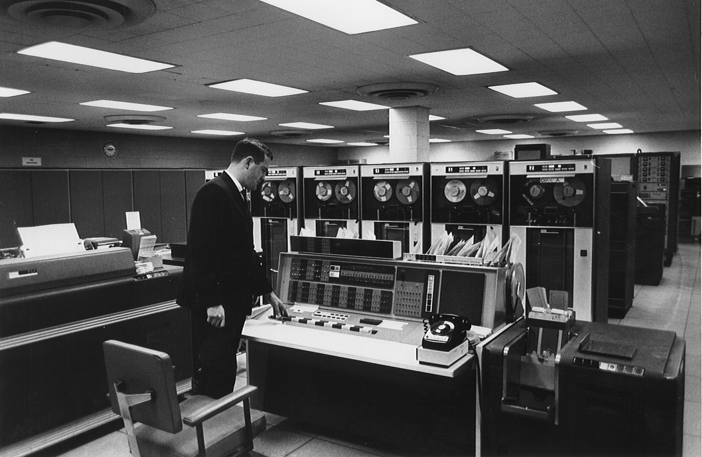
Another view of the IBM 7094 area of the machine room. The operator is John Szallasi.
CLICK ON IMAGE to enlarge.
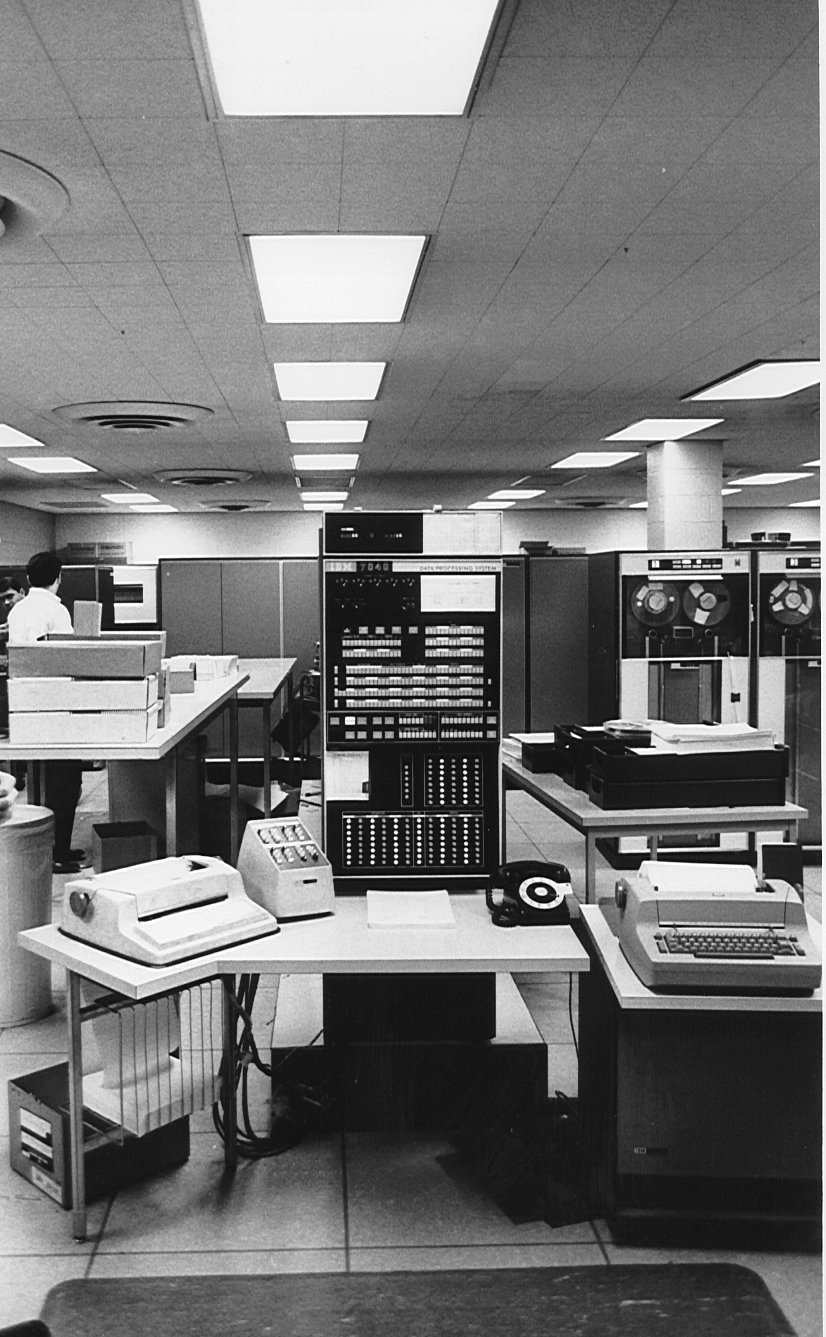
The IBM 7040, the physically smaller and computationally less powerful, but "master" of the the 7094/7040 Directly Coupled System. Some tape drives are on the right. To the left you can see boxes of punched cards. Each box holds 2000 cards. IBM Selectric-typewriter-based terminals (not 2741s) appear to the left and right, probably locally attached to the 7040 as consoles. Peter Capek says, "the box to the right of the other Selectric (on the left end of the console) with a sloped top is a tape switch control. It was used to control relays built into the bottom of the tape drives so that each drive could be connected to either the 7090 or the 7040. (This in lieu of a more appropriately shared medium.) So the implementation of SPOOLing included switching drives back and forth with that box. (I vaguely recall there were 4 buttons for each drive, 2 for each connection and 2 for a 'disconnect' from each side.)"
CLICK ON IMAGE to enlarge.
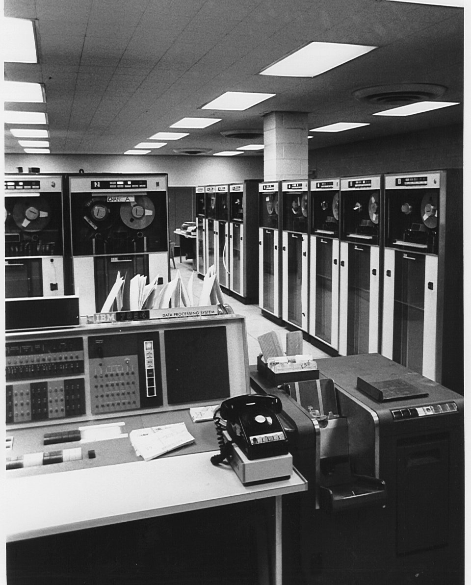
A closer view of the 7094, showing another bank of tape drives and the operator's "personal card reader". Peter Capek writes, "the box under the telephone (about 3 inches high) is part of the console.... it's a pair of "clocks" that record the time the machine is in use, by the customer and by the IBM customer engineer, who had a key that he could use to switch clocks. This was used for machines on rental (in those days, all) and could affect the monthly charges."

The people in this photo are standing in front of the bubble (cloud) chamber film reader / image analyzer. I believe the reel-to-reel drive in the center holds film rather than magnetic tape. In the foreground is a heavy-duty production card reader -- notice the huge input hopper. Peter Capek writes, "The bubble chamber film reader was called the HPD -- Hough-Powell Device (Hough = huff), and the application that ran it (at least in later days, when the /91 arrived) was called HPDOASIS (something like HPD Online Automatic System ... ...). I don't think the drive in the front was a film drive. I recall the film being more exposed and running through a horizonal path, perhaps behind the back in the photo. The card hopper in the foreground is that of a 1402 reader and holds 3000 cards (1.5 boxes). I just searched on Google for Hough-Powell, and there seems to be some stuff there, including CERN archives." [Also see: Bubble Chambers, Technology and Impact on High Energy Physics by Gert G. Harigel.]
There seems to be some doubt about this picture. Ken King, the first Director of the Computer Center says this "does not look like the HPD at the Computer center as I remember it. The HPD was in the back of the computer room and was installed after the 360/91 was installed." [65].Ralph Pisani, who was on staff in 1965, says "The photo of the 'HPD' is totally incorrect. This was the Institute of Defense Analysis project. John Alvarez is the one at the far left and Nat Howard is the middle figure. An I.D.A. employee is probably the one demonstrating the system. The real HPD sits behind the hardware. One can barely make out the Department of Waits and Measurements' film transport system that the HPD used for both its 35mm and 70 mm bubble chamber film. I was the last of the HPD staff to produce data from it. The HPD was prematurely terminated by some six months when I was laid off in January 1980 because Prof. Baltay had been induced into believing that the remaining HPD staff could run the system. Reality had it that the remaining HPD staff was never involved in its day to day operations."
Both Ken King and Mike Radow, however, state that IDA had its own computing facility in the Sheffield Dairy building (Prentis Hall) on St Claire Place (125th Street). Ken says "the HPD worked very well at the Computer Center. Nevis bought an IBM 7044 dedicated to running it and moved it to Nevis so that they could run it 24 hours a day." Columbia cut off relations with the IDA in 1968.
CLICK ON IMAGE to enlarge.
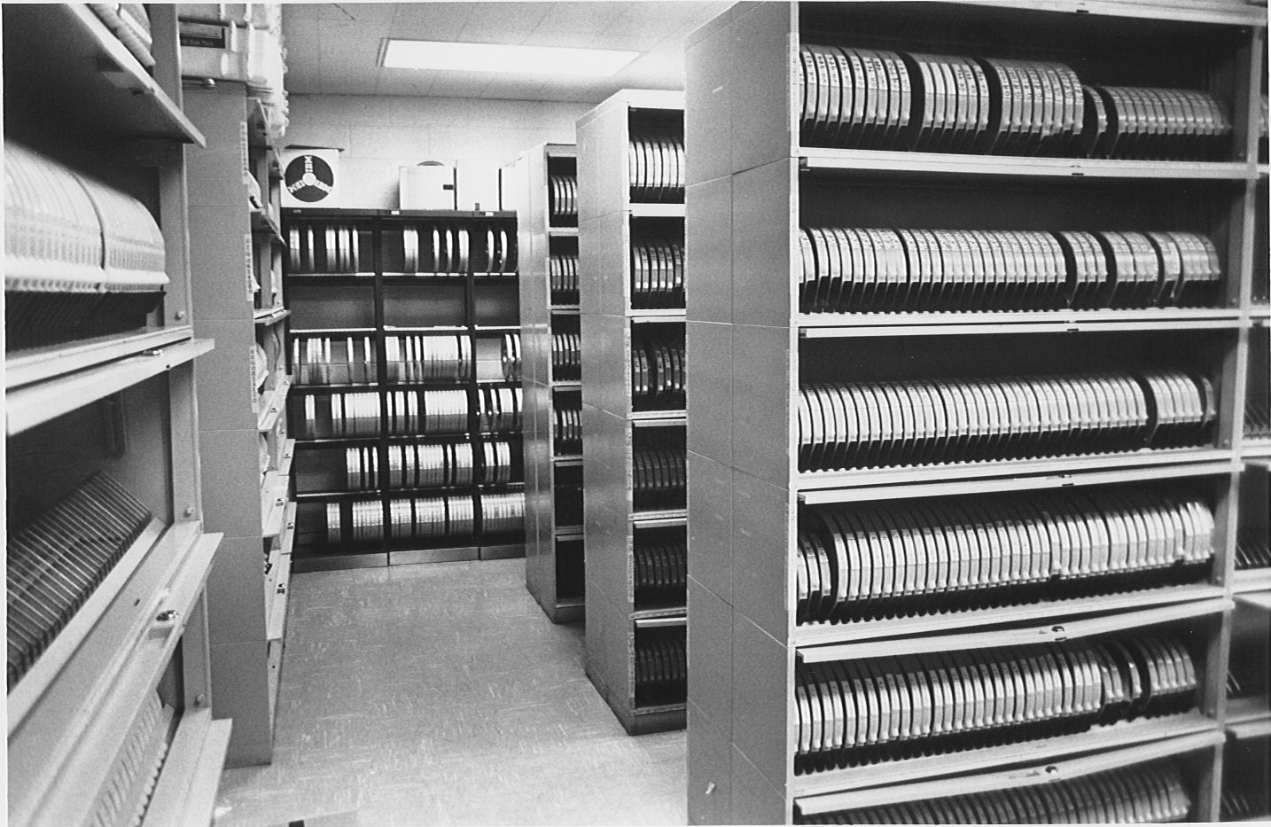
Part of the tape library. It became much fuller as the years passed. These are 10.5-inch (and smaller) reels of half-inch wide magnetic tape, probably 7-track. 9-track tapes would come later, then IBM's Mass Storage System, and finally no tape at all.
CLICK ON IMAGE to enlarge.
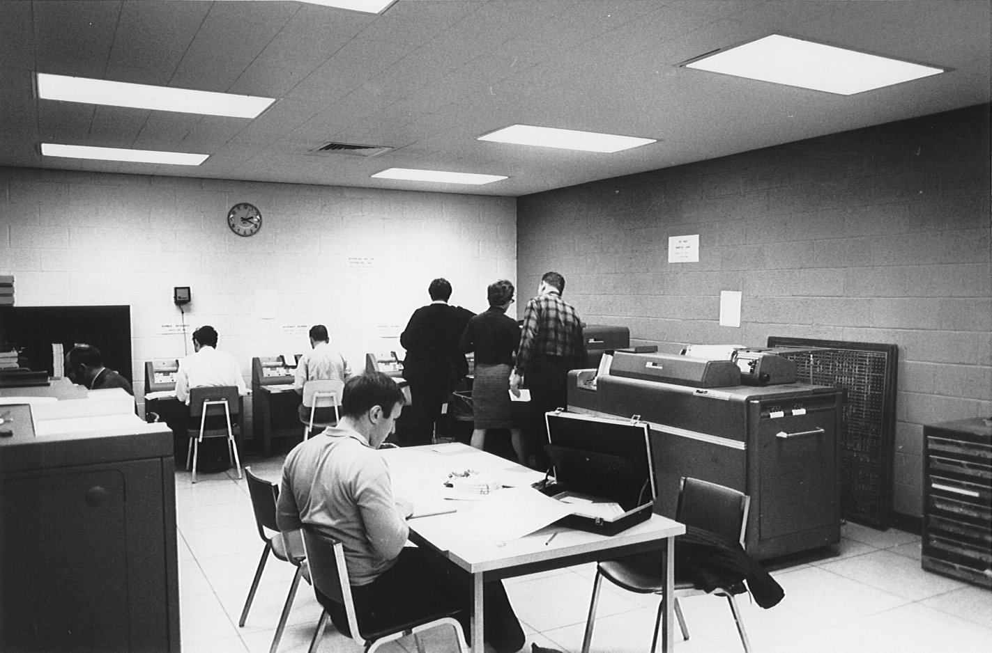
This is the key punch room in the Computer Center, where users could prepare their card decks using the key punch machines against the back wall. An IBM 407 is on the right. On the far right is a cabinet containing IBM 407 control panels -- i.e. plugboard programs -- one for each common function. Behind the 407 is a chalk-board image of a control panel, perhaps that of the 407, used for teaching and designing. CLICK HERE to see a control-panel chalkboard in action.
CLICK ON IMAGE to enlarge.
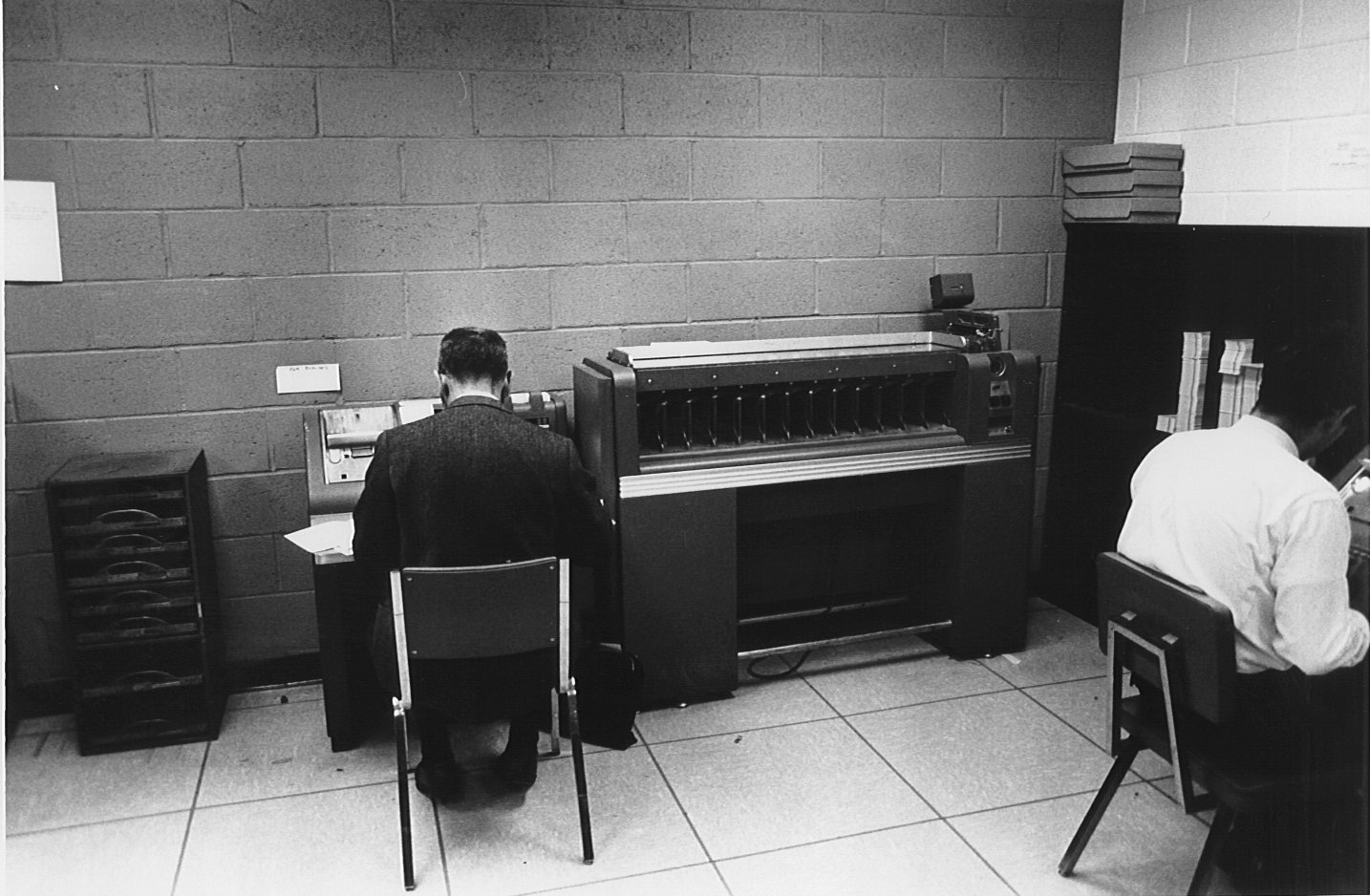
Another scene from the key punch room. Right center is an IBM Type 82 card sorter. To its left is a rack of control panels for one of the EAMs in the room, probably the 407 (but not the sorter, which was controlled by dials).
CLICK ON IMAGE to enlarge.

Another view of the key punch / EAM room.