")
612 West 115th Street, New York NY 10025 USA • [email protected]
| …since 1981 |
| Home | Kermit 95 | C-Kermit | Scripts | Current | New | FAQ | Support |
|
|
The Kermit Project |
Columbia
University
612 West 115th Street, New York NY 10025 USA • [email protected]
| ||||||||
| |||||||||
Frank da Cruz, The Kermit Project, Columbia University, New York City, 28 Nov 2006.
A brief synopsis of portions of Using C-Kermit, Appendix II, "A Condensed Guide to Serial Communications", which may be consulted for greater detail. Portions Copyright © Digital Press.
| • The RS-232 Standard | • Description of Modem Signals | • Modem Connections | • Direct Serial Connections |
Each way requires a different kind of cable. Connections between a PC and a modem use a modem cable (in which wires go "straight through", pin to pin), whereas connections between two computers use a null modem cable (in which pairs of wires are cross-connected). To complicate matters, different kinds of connectors might be needed on each end. While the DCE port is almost always a female DB25, and the PC port is always supposed to be of male gender, the PC port can take many shapes: DB25, DB9, Din8, RJ45, USB, etc; thus many combinations are possible.
Connecting a serial port to an external modem is usually straightforward because all external modems have the same data connector (female DB25) and for every kind of computer that has a serial port, no matter what the connector type, a modem cable should be available (usually from the computer manufacturer).
Connecting two computers together, however, can be more challenging.
The RS-232 Standard
The Electronic Industries Association (EIA) RS-232 standard has been a
universal, stable, and enduring method for connecting computing and/or
terminal devices together for decades; everything else just seems to come
and go. The standard describes a number of electrical signals, each carried
on its own wire (circuit) between DTE and DCE. Although RS-232 does not
specify connector configurations, two have become de facto standards: DB25
(a 25-pin connector, in which usually no more than 10 wires are used), and
DB-9 (a 9-pin connector, in which usually all 9 wires are used). The table
shows the circuits used in computer/modem connections.
| Circuit | V.24 | Name | Direction | DB25 | DB9 | Description |
|---|---|---|---|---|---|---|
| FG | (1) | Frame Ground | 1 | – | Electrical safety | |
| TD | 103 | Transmitted Data | To DCE | 2 | 3 | Data from computer |
| RD | 104 | Received Data | To DTE | 3 | 2 | Data to computer |
| RTS | 105 | Request To Send (2) | To DCE | 4 | 7 | Hardware Flow Control |
| CTS | 106 | Clear To Send | To DTE | 5 | 8 | Hardware Flow Control |
| DSR | 107 | Data Set Ready | To DTE | 6 | 6 | DCE on and in data mode |
| SG | 102 | Signal Ground | 7 | 5 | Voltage measurement reference | |
| CD | 109 | Carrier Detect (3) | To DTE | 8 | 1 | Modems are communicating |
| DTR | 108 | Data Terminal Ready | To DCE | 20 | 4 | DTE on and in data mode |
| RI | 125 | Ring Indicator | To DTE | 22 | 9 | Phone is ringing |
|
The TD and RD wires carry the data, the Signal Ground wire allows the
signals on the other wires to be measured, and the other circuits monitor
the state of the connection.
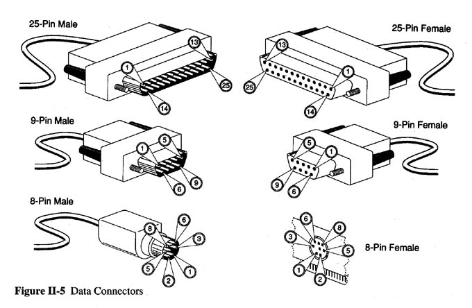
Figure II-5 from Using C-Kermit shows three common connector types (DB25, DB9, Mini Din8), with the pin numbering for used for each gender. As you can see, the two genders are mirror images of each other so when they they mate, pin 1 connects to pin 1, pin 2 to pin 2, and so on. |
|
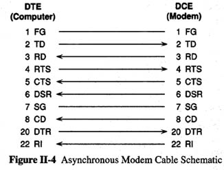
A modem cable is simple and the various signals do their jobs in a
straightforward way. The cable must convey all the signals listed in the
previous section, plus Signal Ground (and Frame Ground for electrical
safety) for a modem connection to function properly.
Most computers have a male serial-port connector, either DB25 or DB9. If it is a DB25, then all the wires in the cable are "straight through", pin 1 on one end to pin 1 on the other; 2 to 2, and so on as shown in the figure. Wires for pins 9-19 and 23-25 might be missing from the cable since they are generally not used. If the computer has a DB-9 connector, then the wires connect the corresponding pins as shown the table above: 2-to-3, 3-to-2, 4-to-7, and so on. |
|
Computer and terminal serial ports are supposed to be male, so the computer
end of a regular modem cable is female. In case the serial port has a
female connector, you can buy a
"Gender Changer".
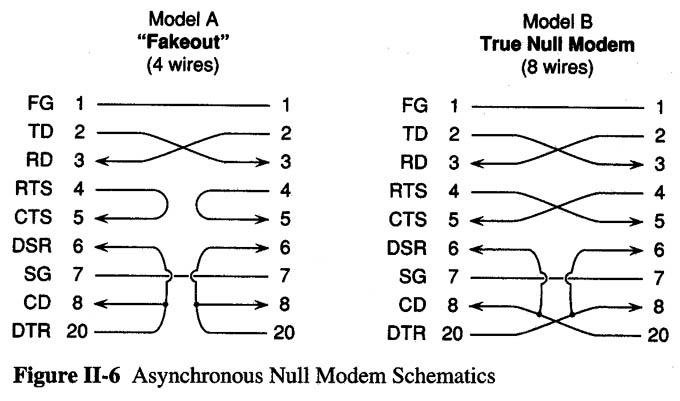
Direct Serial Connections (DTE to DTE)
When two computers (or other DTEs) are to be connected directly, each one
must be "tricked" into thinking the other is a modem (DCE). The trickery is
done entirely with the wires that connect the pins. The result is a
null modem cable – a cable that presents itself to each computer
as if it were coming out of a modem. There are several classes
of null modem cables, each with many variations:
The figure shows the connections for DB25 connectors; use the table above to get the corresponding pins for DB9.
|
By the way, although it was common in days gone by for us to build our own cables, it is (and was even then) much easier to simply buy a "modem eliminator" or "null modem adaptor" from a computer supply store (search). This is a double ended connector that already has all of the Model B crossovers implemented inside. They come in male-male, male-female, and female-female varieties. Attach a regular modem cable to each computer and then interconnect the two modem cables with the modem eliminator. |
The modem eliminator that you want has a connector of the appropriate shape (DB9 or DB25) and gender (male or female) on each end, and is asynchronous, NOT synchronous. A synchronous null modem is something else entirely, with electronics, clock pulse generators, and so forth.
For greater detail, see the Kermit books.