Design and Manufacturing
Our device is a small hybrid compressor/combustor that goes about compression in a novel way. Unlike constantly turning the flow 90 degrees from axial to radial we have a horizontal chamber system that uses sudden openings and closings to go about compression. The word shock wave is used as a synonym for expansion and compression due to rapid changes or pressure gradients or in short: sudden openings and closings of the housing. When we are concluded, we would have created a novel compressor that forms a basis to make a Wave Disk Engine.
Preliminary Design
Currently, the senior design group is responsible for the design and manufacture of a prototype that can show the pressure changes within a chamber – one that simulates a correlation to the theoretical models. Along with designing the prototype, we set design parameters such as chamber dimensions, rpm, mass flow rate, etc. that are then taken by the CFD analyst in the research group to create an appropriate model. These models may or may not show a full hammer-shock wave [the higher the RPM the more clearly shock waves are seen], and the second tier of our design goals in our design review is to create a prototype that can read the pressure changes without necessarily showing shock waves. Currently our models show shock waves at high RPMs of fifteen to twenty thousand; our goal is to have our design show shock waves with an inlet of between one to two ATM air and RPM of between three and fifteen thousand. The smaller our design is the higher the RPM must be, we are constrained to using 12X12 plates of steel or aluminum due to budget and this affects how well our compressor works at low RPMS. Our third tier proposal will show a completely modular design. Our design goals include reducing the leakage from the chambers, which would account for discrepancies from the theoretical models and the prototype.
It is important to note that in the efforts of risk mitigation the design is in a constant state of change. The design initializes the CFD environment and testing; if things must be optimized, the design then modulates to reflect that need. This is our second iteration of the design.
The primary points of concern lay in the inlet set up, outlet shape, the ability to be modular, as well as the tolerance between the parts. The client wanted the ability to have the set up be disassembled easily, from this we went about creating a locking mechanism for the motor shaft and the rotating element without welding the design.
From literature research, we found that the chamber width to chamber length ration must be greater than 10 in order for shock waves to propagate well. We want to have a design close to rectangular chamber, while allowing a ball end mill to fit in between the impellers for manufacturing. It has been argued that having an expanding channel will allow reflected shock waves to become stronger as it reflects from the end to the inner part of the device. We have already undergone stress analysis under 10 passes to 1% convergence of about one million equations to find the displacements to the impellers. This analysis is necessary before the housing design is finalized. The housing design also depends on the CFD work to decide the inlet and outlet geometry. An important note is that the CFD work is in 2D for the moving mesh and in order to have our design accurately model our CFD concept we need to limit the height of the design. In addition to the fact that we will no longer be designing for combustion to take place, the larger tolerance and added mass for thermal expansion will no longer be necessary. From this we will thin out the bottom of the design to help in the balancing of the rotation.

The primary concern for the outer housing is the geometry and relative locations of the inlet and exit, in addition to how the housing and the rotating element would be put together. The relative location of the two to each other decides the propagation of shock, proper purging and proper inlet compression. This work in design will start the CFD environment but must remain flexible to change. The inlet design was large enough to fit a pipe fitting in the top plate to connect to an air hose or compressor. The inlet was refined to slightly diffuse and turn the fluid, meaning there will have to be a curved feature changing the direction of the flow 90 degrees and slightly guiding the flow along the rotational axis to impact the impeller squarely.
Current Design
The following is our eighth complete redesign. It is clear to see that our latest design iteration, D8, has morphed to reflect a modular perspective, as well as ease of manufacturing and assembly. We have made certain areas thinner but in exchange we will use steel for its strength and lower costs per the size we need. Due to budget constraints, sizing and material selection was critical. In addition to the change in inlet pressure to handle up to 24atm gauge, we needed to use stronger material and reassure ourselves through structural analysis that the safety factor was within acceptable limits. Through some review we decided to keep our safety factor above four for each part, trying to have a high factor for higher pressures later in the design life. The modular design also helps lend to the budget constraint as well as the need for the ability to modify the design mid testing.

Top and bottom plate
The new constraining plates were made to lower cost of the housing. These 10 degree separated holes in the design allowed for the whole system to be moved in degrees of ten whether this included the exit angle of adding or subtracting surrounding plates or changing the relative angle between the inlet and exit. Each of these changes had an effect on the fluid flow from our CFD analysis.
To alleviate contact friction between the impeller disc and the lower housing we included slots for ball bearings. To account for the need of a modifiable inlet and outlet geometry and relative angle displacement we have made the radial direction of the housing modular and the inlet to be able to be rotated to give varying angles of opening to affect mass flow rate.
The 90 degree angled lips are to increase surface area contact where we would lay a bead of industrial adhesive and silicone to help halt leakages. The reason the bottom plate is cut out inside is to allow for the motor shaft to rotate the inside disc while allowing for an excess bleed to prevent our system from exploding due to pressure buildup from a sudden stoppage of the blade hypothetically getting seized up in the housing.
Surrounding housing
Shying away from the original 60 degree angled inserts we chose to do overlaying lips for our housing design, with three capable screws on the top and bottom. Our stress concentrations were in the said corners however using a mill to manufacture this will cause us to have rounded corners. The stress concentrations were in acceptable levels, which will be detailed in the stress section. The mated faces will have a thin layer of silicone. Rubber gasket material may be used for the bottom plate if leaking becomes an issue. Previous research showed that typical critical exit angles were greater than 110 degrees and fewer than 130 degrees for a nominal form of 120 degrees. These changes can be achieved through the addition of one of the housings and end bit.
Disc
The tips of the impeller are notably thicker in which we hope to limit expansion by increasing the mass at the localized area. From our displacement test at the tips we also tested the inlet deflection of the blades due to increasing inlet pressure. Our discs were in good standing at the six atm inlet pressure and saw notable deflection at 12 atm and bad deflection at 14 atm. We tested to the pressure of 28 atm since the air tank we will use is compressed at that level; this is to account for a failure with the regulator.
Inlet
Concluding from our CFD analysis we find that the angled opening of the inlet and exit must be larger than the initial assumed ninety degrees to have sufficient time to fill the chamber at high speeds, in addition the relative angle of the inlet to the outlet must be smaller than the initial design of fifteen degrees. Currently we will have a ten degree separation and a one hundred twenty degree inlet and outlet. To help create better mass flow we chose a larger inlet area for the impellers. To help increase a small pressure rise we made the inlet have a diffuser effect; however, its affect will most likely be negligible.
Exit
The only need for the throttle is to unify the chaotic flow of the exit to normalize it for pressure reading at the end. In our scope we are primarily concerned with finding a pressure wave inside the chamber not an overall pressure rise at the exit port; therefore the need for a throttle exit is not necessary but good for further research.
Base
The base will be made from a sturdy desk and will be weighed down with 100lbs of steel to prevent vibration during high rpm testing. The bracing will be made out of structural steel strut channels and L bars.
Motor connection
Due to the size of the motor shaft, we will need to make our own universal hub appropriate to its diameter and length. This hub engages the shaft to the disc and evenly distributes the force applied to the disc from the motor.
Fittings
Each screw was chosen with an acceptable grade and tensile stress rating capable for the system. The choice was ¼” -20 screws that are ranging from ½” – 1” in length. The reason hex cap screws were chosen was that if the screws were stuck or striped a wrench could be used to pull it out.
Sealant
Perhaps the most important factor of the design is the sealing of it. At each mated surface we had a thick layer of industrial strength adhesive made out of silicone. Each component was press fit and the sealant was left to fill the spaces and squeeze through the crevices and set for 24 hours to cure. When the motor was turned on any excess silicone on the inside was churned up and expelled while the excess on the outside was left as it. This helped greatly for sealing the structure; however, it was a temporary solution. Once the geometries are finalized military grade sealant such as sikaflex can be used to permanently set the modular design. The issue of preventing leakages in a pressure vessel is very difficult all the more so with a rotating vessel such as the Wave Disk Generator.
Bearings
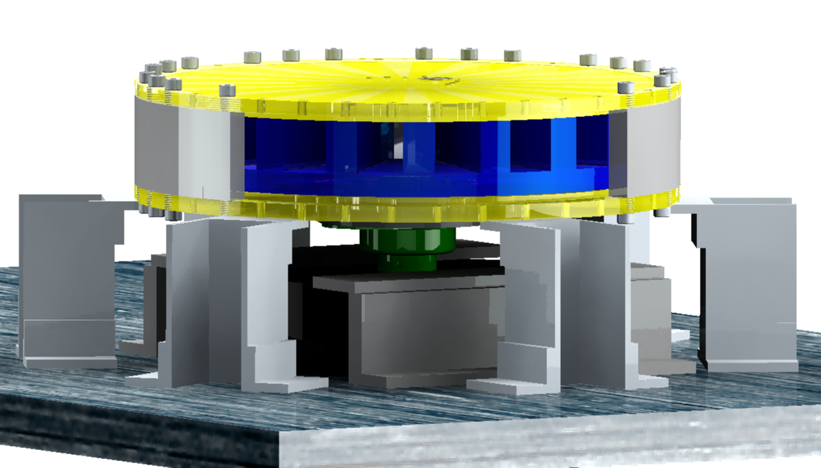
We took on safety and alignment seriously by adding two capable thrust bearings, one radial shaft bearing, and one mounted sleeve bearing for the motor shaft. The needle thrust bearings are optimal for our design since they have greater contact surface area and allow for high rpms with high axial loads, in exchange they are at a higher price. The top thrust bearing acts as a constraint for the disc in the positive z direction, the second separates the disc from the bottom housing and constrains in the negative z direction taking into account the top and bottom and inlet are fixed due to being the outer housing. The last thrust bearing is just to limit friction between the shaft connection and the disc and the shaft. Lastly, we opted for the mounted sleeve bearing instead of a normal bearing since it did not inhibit the design as it is located outside of the housing: it helps to constrain radial movement and is rated for higher rpms with axial/radial loads.

Needle bearings In red
8500lbs axial dynamic loading at 5000rpm max
Ball bearings in green
Radial 2273 lbs loading, at 9300 rpm
Mounted sleeve bearings Bottom green
Radial 1870 at 3000 rpm
Each of these were sufficient for our design.
Manufacturing and Assembly
Taking into account material costs, time constraints, and material properties, two prototypes were manufactured: a metal prototype and an ABS plastic prototype. The metal prototype, made primarily from steel with a few aluminum parts, was manufactured using the CNC milling and lathing machines available in the Mechanical Engineering Undergraduate Lab. To ensure the parts manufactured conformed to drawing specifications, the parts designed in PTC Creo were converted from .prt files to .IGES files for the purpose of importing the files to MasterCAM X6. Before generating the projected tool paths using MasterCAM, the proper cutting tools and feeds and speeds for the stock materials were chosen. The Machinery’s Handbook was used to calculate the proper feeds and speeds required to properly mill and lathe the steel and aluminum stock. The steel acquired was ASTM A36 hot-rolled low-carbon general purpose steel. Since ASTM A36 was not listed in the Machinery’s Handbook, the feeds and speeds were calculated for AISI 1212 steel, which has the most similar properties to ASTM A36. The steel purchased was more difficult to machine than expected, possibly due to the methods used for cutting the stock (plasma cut and shear cut), leading the group to invest in end mills that were used to cut the steel. The tools purchased were a ½ in. roughing/finishing solid carbide end mill with an AlTiN coating, a ¼ in. square solid carbide end mill with an AlTiN coating, and a ¼ in. roughing cobalt end mill with a TiN coating. With the tool material and the stock material chosen, the feeds and speeds were calculated using tables provided in the Machinery’s Handbook. The tool paths for these cutting tools were then generated in MasterCAM and posted from MasterCAM to the Fryer CNC controller. The following figures show models and tool paths from MasterCAM:


Due to long machining times for the steel plates, a 3D printed prototype was manufactured to assemble a prototype for troubleshooting and preliminary testing purposes. The PTC Creo .prt files were converted to .stl files and imported into the Stratysis Fortus 3D printer control software available in the Mechanical Engineering Undergraduate Lab. The parts printed were manufactured as solid ABS plastic parts to increase the material strength to the necessary properties for preliminary testing. Due to budget constraints and for the purpose of consistency between the two prototypes, the bolts acquired for the steel prototype were used for the plastic prototype. Since these bolts were not specifically chosen for use with a plastic prototype, after assembly and troubleshooting the plastic walls experienced stress fractures caused by the bolts used to assemble the parts.
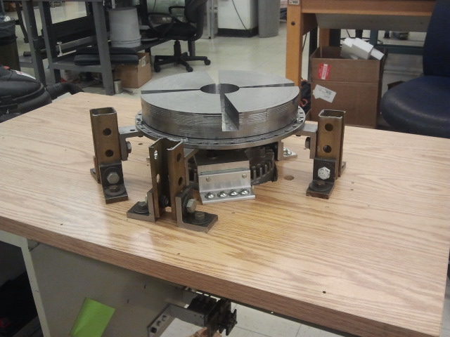
To secure the Wave Disk Generator, cautionary steps were taken into consideration during mounting. The motor was first mounted to the desk using 6 L brackets made of Aluminum 6061. Each bracket was 4 inches wide with a height of 2 inches and a thickness of 0.25 inches. Two brackets were bolted together with 3 bolts to create a Z-shape. These Z brackets were then mounted to the motor using two 3/8” thick bolts for each Z bracket. At the bottom of the Z-bracket four ½” inch thick bolts for each to be mounted to the desk. Now the housing of the Wave Disk Generator was mounted using five 3.6 inch long strut channels and three L brackets. Two L brackets were placed on each side of the strut channel to the table. They were bolted down to the table using a 5/16” thick and one 5/16” bolt to the strut channel for each of the two L-brackets. The third L-bracket was mounted upside down and mounted to the bottom of the housing a ¼ “ screw the same as the walls. It was mounted to the strut channel using a 5/16” bolt like the bottom mounts. These strut channels and brackets acted as pillars to support and balance the housing of the wave disk generator. Stress analysis showed that they were capable of withstanding the weight of 3 housings and discs, so there was no doubt about structural integrity.